Fluid pump

a technology of fluid pump and pump body, which is applied in the direction of pump, positive displacement liquid engine, machine/engine, etc., can solve the problem of substantially unaffected delivery and achieve the effect of minimizing leakag

Inactive Publication Date: 2008-12-25
DELPHI TECH INC
View PDF24 Cites 0 Cited by
  • Summary
  • Abstract
  • Description
  • Claims
  • Application Information

AI Technical Summary

Benefits of technology

[0022]The plunger is preferably circular in cross section, chiefly for convenience of design and manufacture, and to minimize leakage past the plunger, in use.

Problems solved by technology

However, at higher pump speeds deliv

Method used


Image

  • Fluid pump
  • Fluid pump
  • Fluid pump

Examples


Embodiment Construction

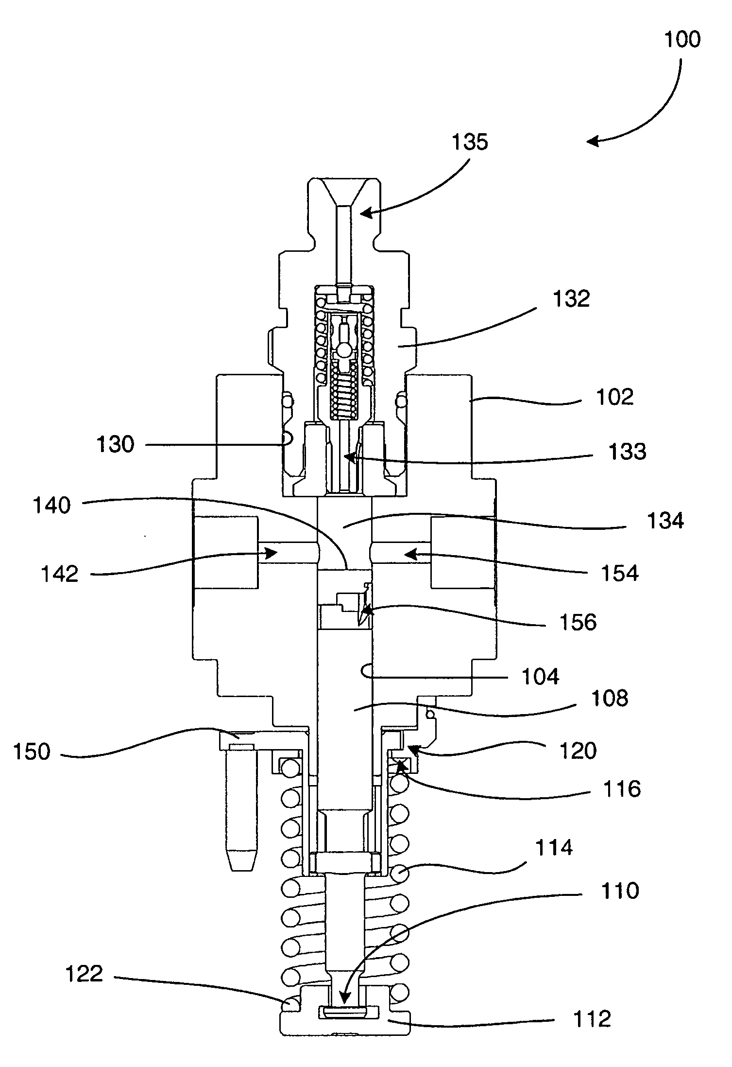
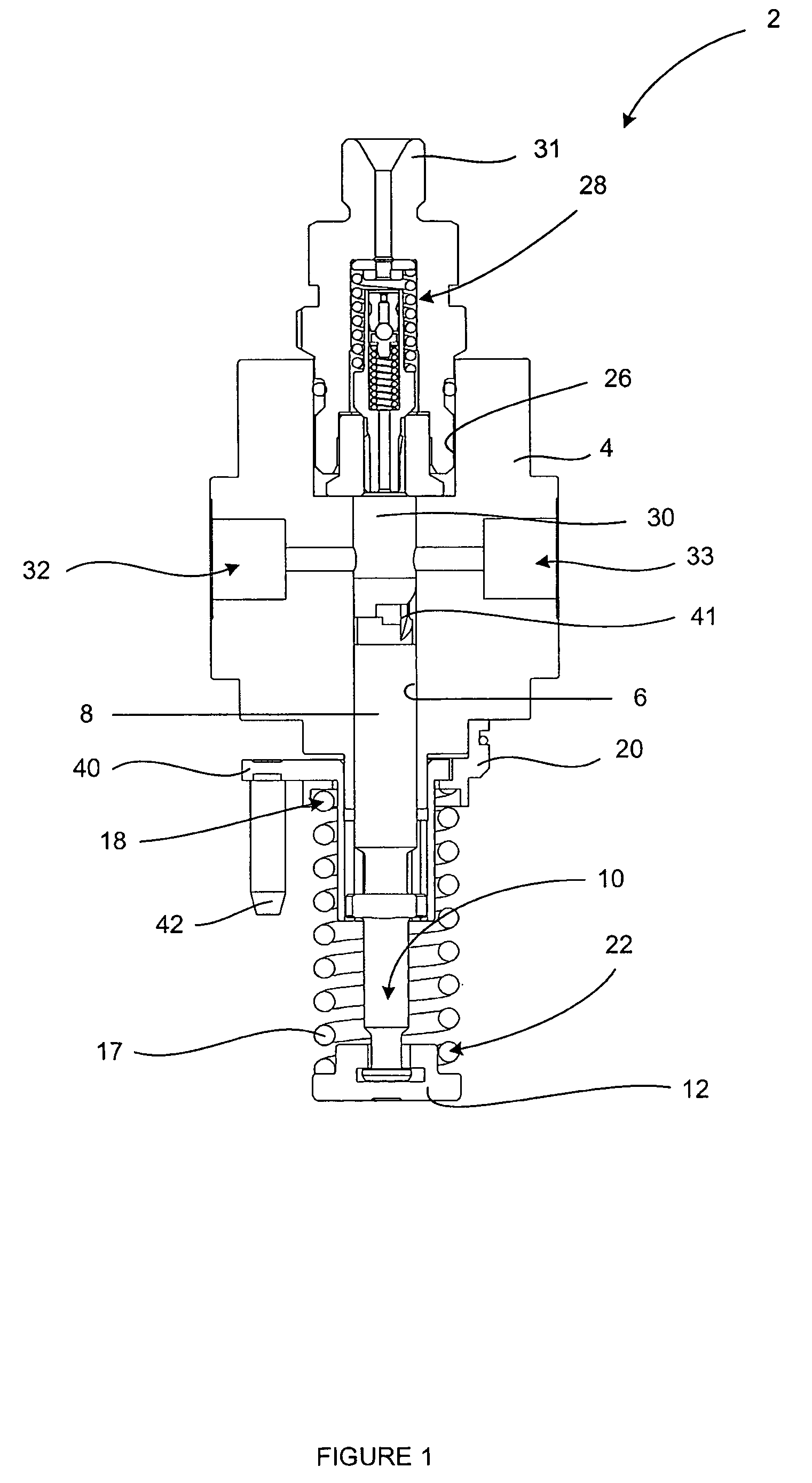
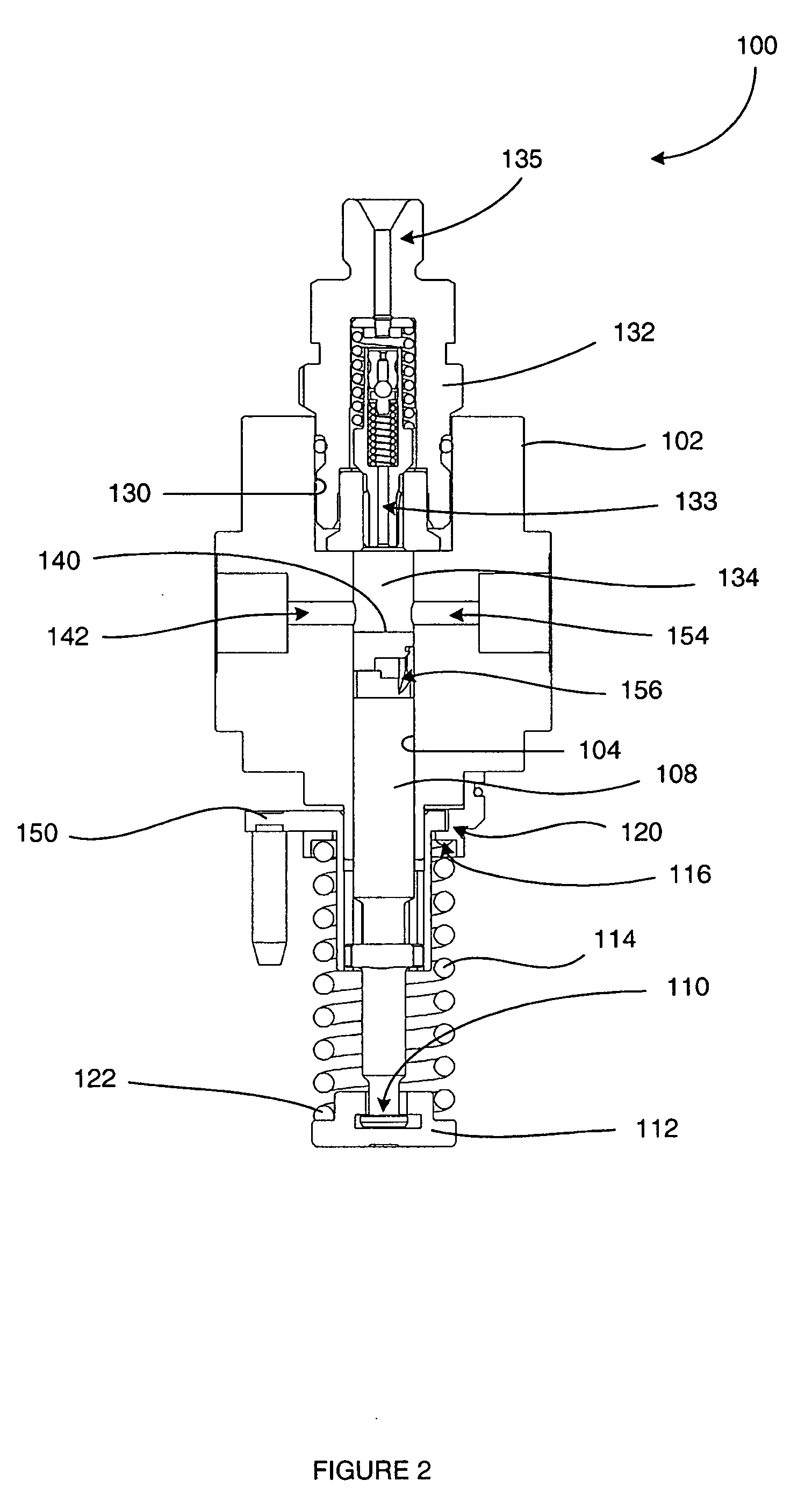
[0032]Referring to FIG. 2, a mechanical fuel injection pump 100 (hereinafter ‘fuel pump’) is shown that is similar to the fuel pump 2 described above with reference to FIG. 1.

[0033]The fuel pump 100 includes a block-like pump body, or housing 102 having an axially disposed bore 104 within which a pumping plunger 108 is slidable. The plunger 108 has a lower end 110 (in the orientation shown in FIG. 2) that is coupled to a lower spring plate 112 for transmitting reciprocating motion to the plunger 108. Although not shown in the diagram, a tappet and cam member (not shown) may be arranged with respect to the lower spring plate 112 such that rotation of the cam member causes reciprocation of the plunger 108. This form of plunger drive arrangement is known in the art.

[0034]A biasing means in the form of a helical spring 114 is received over the plunger 108 such that the spring 114 is disposed between the pump housing 102 and the lower spring plate 112. An upper end 116 of the spring 114 ...


PUM


Abstract

A pump for fluid, comprising a pump body defining a bore, a pumping plunger having an end region which is slidably received within the bore, a spill port defined by the pump body in a wall of the bore which port is coverable by the end region of the pumping plunger as the plunger is driven on a pumping stroke, in use, so as to initiate fluid pressurization within a pumping chamber; and a spill feature defined by the pumping plunger being arranged to uncover the spill port during a pumping stroke so as to cause depressurization of the pumping chamber. The pumping plunger further defines a speed sensitive feature configured to permit a controlled leak of fluid from the pumping chamber to the spill port towards the end of a pumping stoke. The invention also encompasses a pumping plunger particularly suited for use in the above described pump.

Description

TECHNICAL FIELD[0001]The present invention relates to a fluid pump. More specifically the invention relates to a ‘unit pump’ type fuel injection pump for use in a compression ignition internal combustion engine in which a pumping plunger reciprocates within a plunger bore in order to pressurize fuel within a pumping chamber. In addition, the invention relates to a pumping plunger for use within such a pump.BACKGROUND ART[0002]FIG. 1 shows a sectional view of a known fuel injection pump, indicated generally as 2, which is suitable for use as a means of supplying pressurized fuel to a fuel injector of an internal combustion engine. Such a pump is generally known in the art as a mechanical ‘unit pump’. The fuel pump 2 includes a generally tubular pump housing 4 having an axially disposed bore 6 within which a pumping plunger 8 is slidable. The plunger 8 has a lower end 10 (in the orientation shown in FIG. 1) that is coupled to a lower spring plate 12. Although not shown in FIG. 1, in p...

Claims


Application Information

Patent Timeline
IPC IPC(8): F04B39/10
CPCF02M59/102F02M59/265
Inventor FELTON, GEORGE NICHOLASKARAKAYA, NEBI
Owner DELPHI TECH INC
Why Eureka
Try Eureka