
Transmitter and receiver for observing periodical events

a technology applied in the field of transmitter and receiver, can solve the problems of confusion in the receiver device, error in the calculation of displayed information, and difficulty in the management of the receiver device, and achieve the effect of efficient and reliable transmission of data

Inactive Publication Date: 2008-12-25
SUUNTO OY
View PDF7 Cites 34 Cited by
  • Summary
  • Abstract
  • Description
  • Claims
  • Application Information

AI Technical Summary

Benefits of technology

[0008]Therefore, it is an object of the present invention to create a mobile transmitter and corresponding receiver device providing efficient and reliable transmission of data from the mobile transmitter to the receiver device.
[0021]Therefore, the invention provides detection of the observed events and production of data messages containing predetermined number of time references indication the points in time wherein the observed events occurred. The mobile transmitter can proceed straightforwardly and does not need extensive processing power. Therefore, the mobile transmitter can be designed small and power-efficient. The receiver device receives time references and can base its calculations on accurate information.
[0023]Furthermore, it is likely that the consecutive data messages contain overlapping information such that the same time references may occur in two or more of the data messages. This double-transmission of information provides reliability for the transmission, as loss of any single data message does not cause the receiver device being unaware of any of the time references. Thus, the receiver device receives a copy of every single time reference despite problems in transmitting some of the data messages. Such a double-transmission of information can be assured in embodiments wherein the number of time references in data messages and the time period between transmission of said messages are selected such that any one of the time references is included in at least two data messages even when the observing events occur at their maximum expected rate or frequency. However, enhanced reliability is attained already at lower retransmission rates than two. For example, the retransmission rate at the maximum expected rate or frequency of the observed events can be designed as 1.5 wherein enhanced reliability is attained also at the maximum rate. Even when the retransmission rate at the maximum expected rate or frequency of the observed events is about one, there is retransmission at the lower than the maximum rates of the observed events.
[0032]Compared to the prior art solutions, the above-mentions embodiment provides the advantages of both the easy transmission of sufficient data from a remote device (for example, a transmitter belt) to a terminal device (for example, a wristop computer) for it to be possible to calculate the measured variable, such as heart rate, and also of being able to determine if the data received is deficient.
[0033]An embodiment of a heart rate monitor permits the provision of very accurate heart rate data, pulse data or pulse-interval data to a wristop device or computer. Accurate pulse-interval data can be exploited, for example, when calculating variations of the pulse intervals, in a wristop device or computer, in exercise analysis. Pulse-interval data or variation in the pulse intervals can be used to obtain interesting information, for example, on the level of stress of the body.

Problems solved by technology

In the prior art mobile transmitter / receiver device solutions problems may arise in a situation in which information on one or some of the observed events is not transmitted to the receiver device.
It may be very difficult for the receiver device to manage a situation, wherein detection information is missing.
This lack of detection information may lead to confusion in the receiver device and to an error in the displayed information calculated on the basis of such information.
On the other hand, there should not be extensive exchange of information between the mobile transmitter and the receiver device, e.g. due to limitations in size and power consumption of the devices.

Method used


Image

  • Transmitter and receiver for observing periodical events
  • Transmitter and receiver for observing periodical events
  • Transmitter and receiver for observing periodical events

Examples


Embodiment Construction

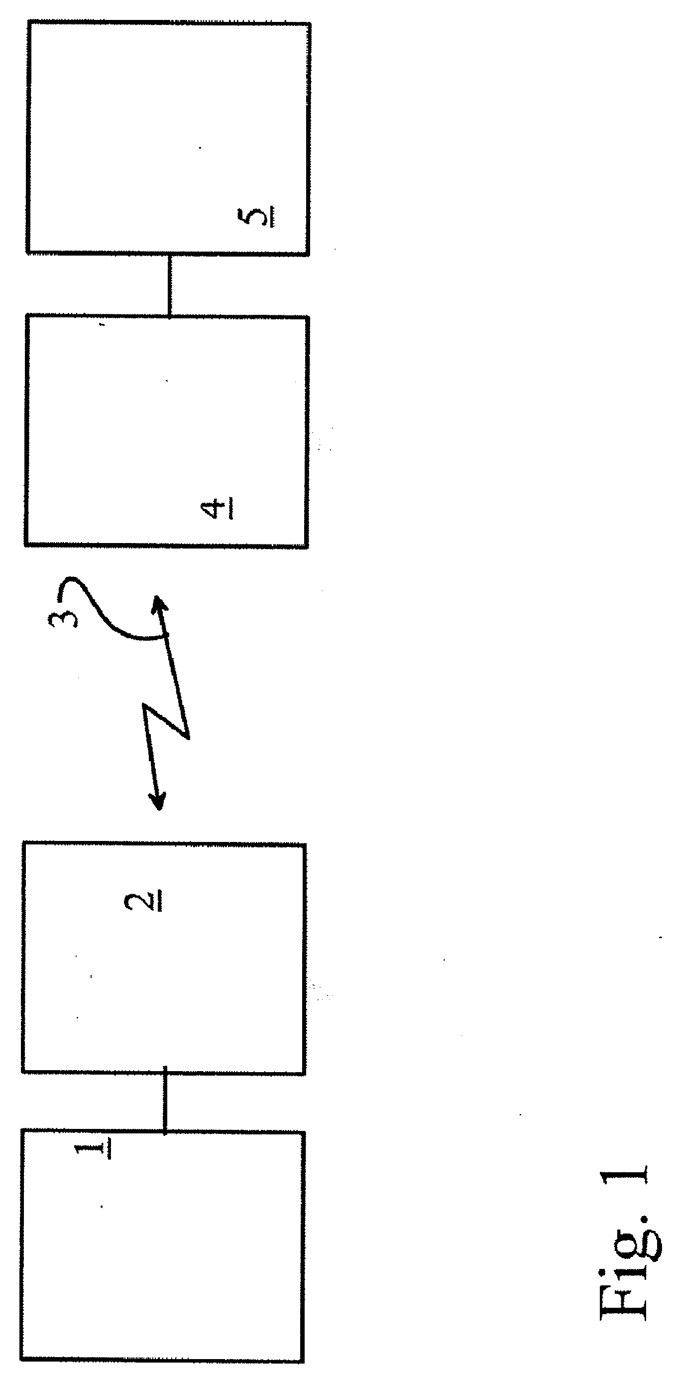
[0039]According to FIG. 1, the apparatus includes a measuring device 1, which is a pulse meter attached to the chest by a flexible belt. The pulse meter in question contains electrodes, with the aid of which the pulse of the person is measured. The measuring device 1 can naturally be some other measuring device. The measuring device is connected to a transmitter / coder 2, in which the measurement signal is edited into a transmittable form and given a code individuating the transmitter 2. The signal is sent from the transmitter 2 wirelessly over a transfer path 3 to a receiver 4, which also includes means for decoding the code. The transfer path 3 is typically the air space between the measuring device 2 located around the chest and a receiver 4 located on the wrist.

[0040]The receiver 4 is, in turn, connected to a data-processing unit 5, to which a display is typically also connected. The receiver 4 and the data-processing unit 5 are typically implemented in a wristop computer, which ...


PUM


Abstract

A mobile transmitter for observing events and transmitting data on the observed events to a receiver and a device for receiving data messages from the mobile transmitter. The transmitter and receiver are designed so as to provide efficient and reliable transmission of data from the mobile transmitter to the receiver device.

Description

CROSS-REFERENCE TO RELATED APPLICATIONS[0001]This application is a Continuation-In-Part of copending application Ser. No. 11 / 169,712 filed on Jun. 30, 2005, for which priority is claimed under 35 U.S.C. § 120, which is a non-provisional application claiming priority under 35 U.S.C §119(e) on Provisional Application No. 60 / 585,225 filed on Jul. 2, 2004, the entire contents of which are hereby incorporated by reference.BACKGROUND OF THE INVENTION[0002]The present invention relates to a mobile transmitter for observing events and transmitting data on the observed events to a receiver.[0003]The invention also relates to a device for receiving data messages from a mobile transmitter.[0004]Such mobile transmitters can be used, for example, in heart-rate monitors. The term heart-rate monitor refers also to a wristop computer or some other corresponding device, equipped with heart-rate monitor properties.[0005]There are also various other fields of use for the mobile transmitters and receiv...

Claims


Application Information

Patent Timeline
IPC IPC(8): A61B5/0404H04B7/00A61B5/332
CPCA61B5/0002A61B5/0006A61B5/02438A63B24/0062A63B2220/12A63B2220/34A63B2220/62A63B2220/64A63B2220/833A63B2225/50A63B2230/06G01C22/006G01P1/07G01P1/12
Inventor JUNTUNEN, JOUNIKEKALAINEN, PANUPIENIMAKI, KAUKOMANNONEN, KALLELINDMAN, ERIK
Owner SUUNTO OY
Learn More