Charge-discharge management apparatus and computer readable medium comprising instructions for achieving the apparatus

a technology of charge-discharge management and computer readable medium, which is applied in the direction of process and machine control, external condition input parameters, navigation instruments, etc., can solve the problems of time-consuming scheduling, difference between scheduled and actual remaining battery capacity, and less effective scheduled control. to achieve the effect of reducing the adverse effect of control

Inactive Publication Date: 2008-12-25
DENSO CORP
View PDF10 Cites 109 Cited by
  • Summary
  • Abstract
  • Description
  • Claims
  • Application Information

AI Technical Summary

Benefits of technology

[0010]The present invention has been made in consideration of the foregoing. It is therefore an object of the present invention to reduce an adverse effect on control due to time-consuming scheduling when the control is provided in accordance with a schedule created by a charge-discharge management apparatus concerning whether or not to operate an internal combustion engine and a motor and to charge the battery along an estimated route.

Problems solved by technology

However, the scheduling is time-consuming.
As a result, the scheduled control becomes less effective.
There is repeated a cycle of scheduling, causing a difference between the scheduled and actual remaining battery capacities, and rescheduling.
As a result, scheduled control is unavailable along the estimated route 63.

Method used


Image

  • Charge-discharge management apparatus and computer readable medium comprising instructions for achieving the apparatus
  • Charge-discharge management apparatus and computer readable medium comprising instructions for achieving the apparatus
  • Charge-discharge management apparatus and computer readable medium comprising instructions for achieving the apparatus

Examples


first embodiment

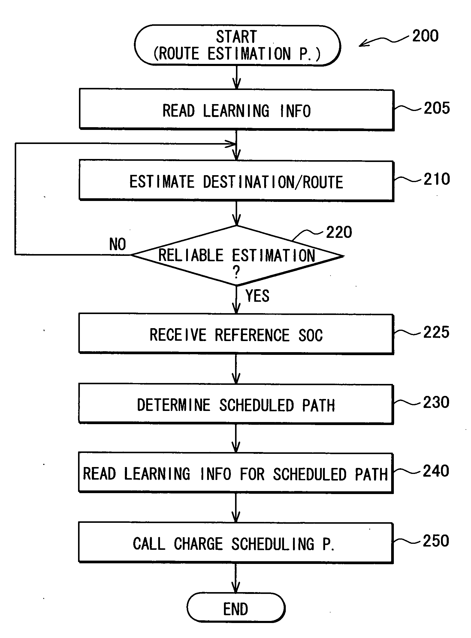
[0029]The following describes a first embodiment of the present invention.

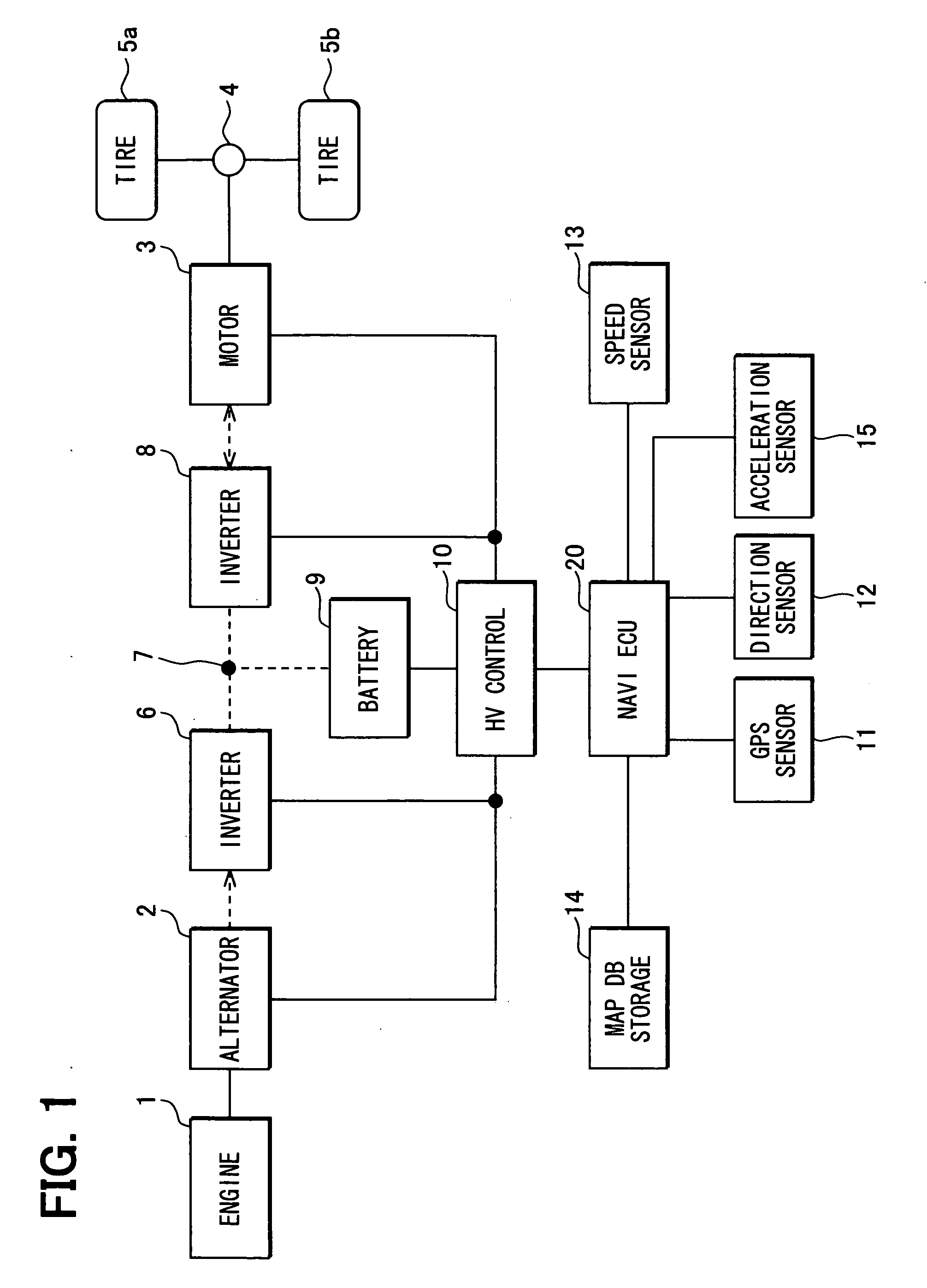
[0030]FIG. 1 schematically shows a construction example of a hybrid vehicle according to the embodiment. The hybrid vehicle includes an engine 1 as an internal combustion engine, an alternator 2, a motor 3, a differential gear unit 4, a tire 5a, a tire 5b, an inverter 6, a DC link 7, an inverter 8, a battery 9, an HV (Hybrid Vehicle) control section 10, a GPS sensor 11, a direction sensor 12, a vehicle speed sensor 13, a map DB storage section 14, an acceleration sensor 15, and a navigation ECU 20.

[0031]The hybrid vehicle runs using the engine 1 and the motor 3 as a power source. When the engine 1 is used as the power source, a rotation of the engine 1 is transmitted to the tires 5a and 5b via an unshown clutch mechanism and the differential gear unit 4. When the motor 3 is used as the power source, a direct current of the battery 9 is converted into an alternating power via the DC link 7 and the inverter 8.

[0...

second embodiment

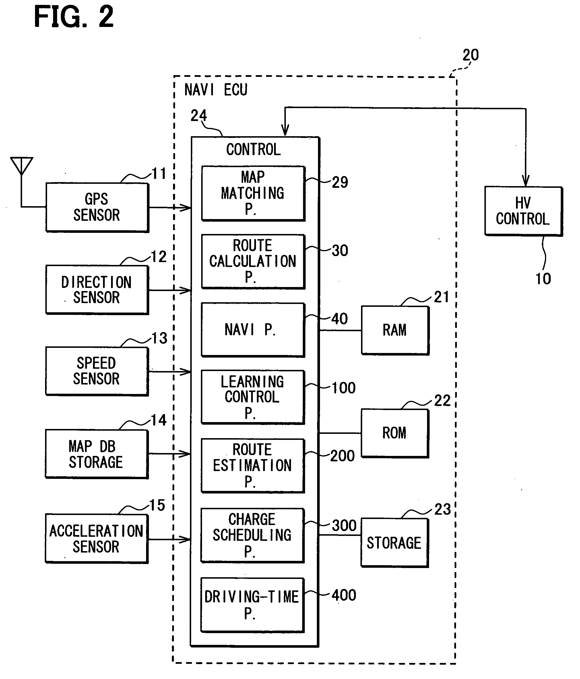
[0088]The following describes a second embodiment of the present invention. The second embodiment differs from the first embodiment in that the control section 24 of the navigation ECU 20 according to the second embodiment estimates a distance (equivalent to an MM distance) for allowing the map matching process 29 to provide an accurate result and reflects the estimation on the determination of the start point on the scheduled path.

[0089]Because of this operation, the control section 24 according to the second embodiment executes a route estimation process 200′ in FIG. 10 instead of the route estimation process 200 in FIG. 5. The steps designated by the same reference numerals in FIGS. 5 and 10 provide the same processes and a detailed description is omitted for simplicity.

[0090]In the route estimation process 200′, the control section 24 performs Steps 205, 208, and then 210 in order.

[0091]At Step 208, the control section 24 determines an estimated MM distance. When the subject veh...


PUM


Abstract

After a final estimated route for a hybrid vehicle is specified, a navigation ECU determines a start point of a scheduled path, which a charging schedule is to be created for. The start point corresponds to a position at a travel distance, which is equivalent to a distance traveled from a present position of the hybrid vehicle along the estimated route for a time period required for creating a charging schedule.

Description

CROSS REFERENCE TO RELATED APPLICATION[0001]This application is based on and incorporates herein by reference Japanese Patent Applications No. 2007-162507 filed on Jun. 20, 2007 and No. 2007-276497 filed on Oct. 24, 2007.FIELD OF THE INVENTION[0002]The present invention relates to a charge-discharge management apparatus for a hybrid vehicle, and further relates to a computer readable medium comprising instructions for achieving the charge-discharge management apparatus.BACKGROUND OF THE INVENTION[0003]There has been provided a hybrid vehicle using as a power source for running (i) an internal combustion engine driven by fuel combustion and (ii) a motor driven by a battery. As disclosed in Patent Documents 1 and 2, for example, a charge-discharge management apparatus is known so as to save fuel consumed by the internal combustion engine of the hybrid vehicle. The charge-discharge management apparatus creates a schedule concerning whether or not to operate the internal combustion engi...

Claims


Application Information

Patent Timeline
Patent Type & Authority Applications(United States)
IPC IPC(8): B60W20/00G01C21/30
CPCB60K6/442B60L58/13B60W10/08B60W10/26B60W20/00B60W2510/244B60W2530/14B60W2550/142B60W2550/402G01C21/3415G01C21/3469Y02T10/6234Y02T10/6291B60L15/2045B60L2260/52B60L2260/54B60L2240/12B60L2240/14B60L2240/32B60L2240/547B60L2240/549B60L2240/622B60L2240/642B60L2250/16B60L2250/26B60L2260/42B60L2260/44Y02T10/7077Y02T10/7044Y02T10/7005Y02T10/705Y02T90/16Y02T90/161Y02T90/162Y02T10/7283Y02T10/6217Y02T10/7291Y02T10/645Y02T10/72B60W20/12B60W20/11B60L50/61B60W10/06B60W50/0097B60W2552/15B60W2556/10B60W2556/50Y02T10/62Y02T10/64Y02T10/70Y02T10/7072
Inventor YAMADA, KAZUNAO
Owner DENSO CORP
Why Eureka
Try Eureka