Eureka AIR delivers breakthrough ideas for toughest innovation challenges, trusted by R&D personnel around the world.

Connection fatigue index analysis for threaded connection

a fatigue index and threaded connection technology, applied in the field of threaded connections, can solve the problems of complex calculations, but are well within the capabilities of ordinary people, and achieve the effect of reducing costs and increasing the life of the tool

Inactive Publication Date: 2008-12-25
TH HILL ASSOC
View PDF3 Cites 17 Cited by
  • Summary
  • Abstract
  • Description
  • Claims
  • Application Information

AI Technical Summary

Benefits of technology

[0012]In view of the foregoing, the present invention is directed to a methodology for considering fatigue life rather than only stress and strain when comparing drill string design options. In accordance with one embodiment, operators will benefit from decreased costs associated with fishing and tool replacement, and drilling contractors and rental companies can benefit from increased tool life.
[0014]For example, in one embodiment, if it is known that a section of 8 inch OD×2 13 / 16 inch ID drill collars are to be used in a bottom hole assembly (BHA), collars equipped with either NC56 or 6⅝ REG connections can be used. Assuming all else but the connection type equal, it is desirable to select a combination which minimizes the chances of fatigue failure. By using ‘relative fatigue design,’ the present invention in one embodiment enables the practitioner to determine that the NC56 connection is three times better than the 6⅝ REG connection (will last three times a long under the same operating conditions).

Problems solved by technology

The calculations are complex, but are well within the capabilities of persons of ordinary skill using presently available computer systems.

Method used


Image

  • Connection fatigue index analysis for threaded connection
  • Connection fatigue index analysis for threaded connection
  • Connection fatigue index analysis for threaded connection

Examples


Embodiment Construction

[0025]In the disclosure that follows, in the interest of clarity, not all features of actual implementations are described. It will of course be appreciated that in the development of any such actual implementation, as in any such project, numerous engineering and technical decisions must be made to achieve the developers' specific goals and subgoals (e.g., compliance with system and technical constraints), which will vary from one implementation to another. Moreover, attention will necessarily be paid to proper engineering practices for the environment in question. It will be appreciated that such a development effort might be complex and time-consuming, but would nevertheless be a routine undertaking for those of ordinary skill in the relevant fields.

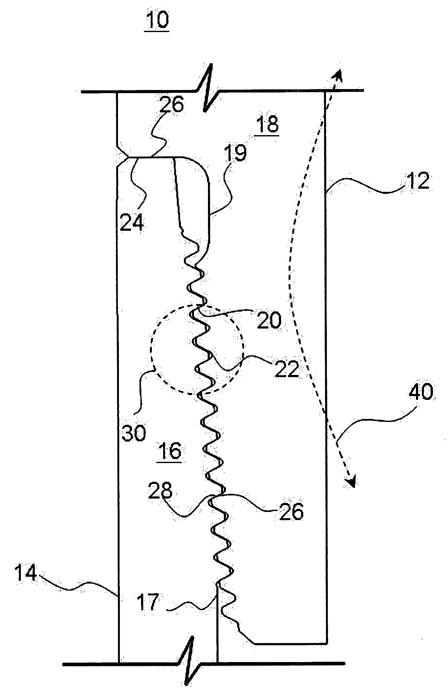
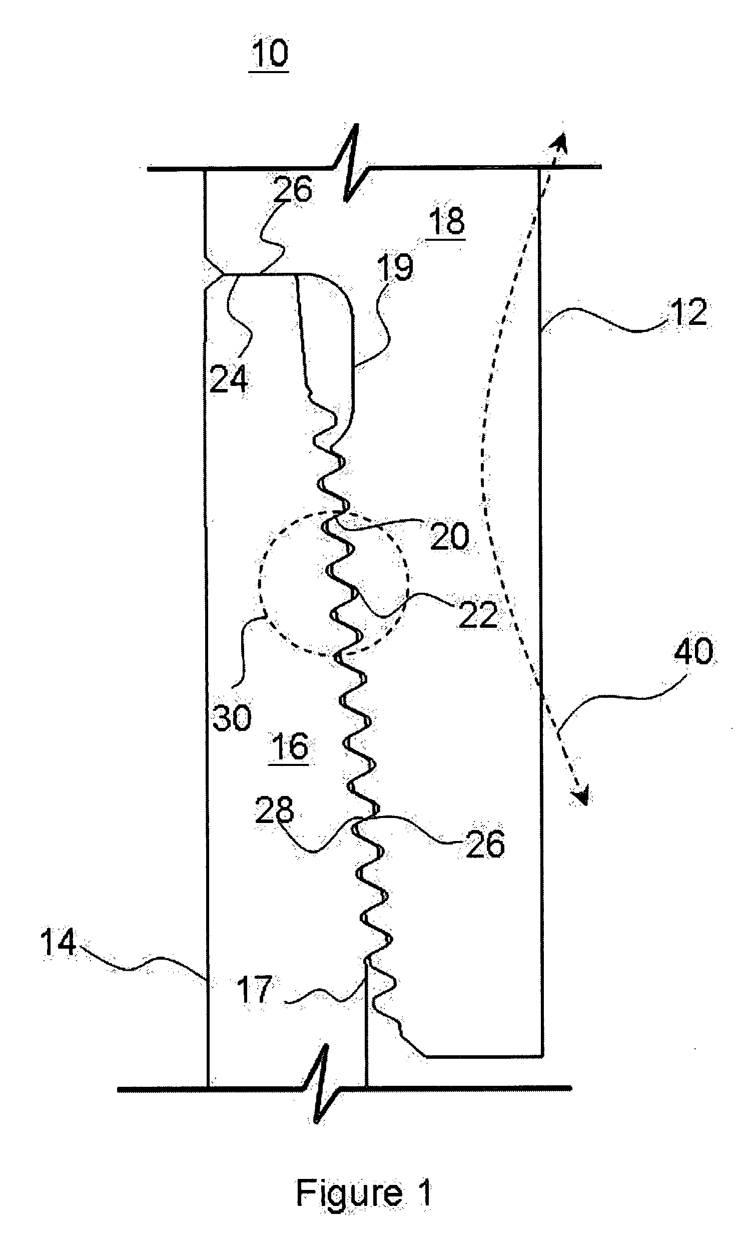
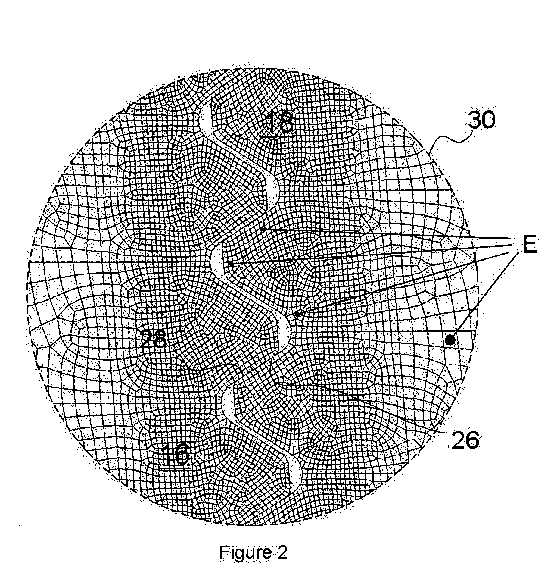
[0026]Referring to FIG. 1, there is shown a side cross-sectional view of a portion of a threaded connection 10 between a first tubular segment 12 and a second tubular segment 14. In particular, and as will be familiar to those of ordi...


PUM


Abstract

A method for characterizing a threaded coupling such as between two tubular members is disclosed. In one embodiment, a threaded connection between a first tubular and a second tubular is considered, where the first tubular has a internally-threaded box structure and the second tubular has outer threads defining a pin structure. A mathematical model of the connection between the two tubulars is generated, and the mathematical model is permuted to reflect application of at least one flexing force to the joint. From the permuted model, a stress / strain distribution of the box and pin structures is derived. A connection fatigue index value is calculated based on the stress / strain distribution. In one embodiment, connection fatigue indices are computed for a variety of connection combinations, such that a user can compare the relative suitability of multiple box / pin combinations to select one that is deemed desirable for a particular use.

Description

FIELD OF THE INVENTION[0001]The present invention relates generally to threaded connections between tubular segments, and more particularly to the threaded connections between individual segments of a drill string used in hydrocarbon exploration and production.BACKGROUND OF THE INVENTION[0002]When designing drillstrings, the designer must specify both the type of connections and whether or not to ensure the use of components including certain stress relief features. It is known that the relative fatigue lives of drill string connections will vary for a number of different reasons, including, without limitation, the drill string dimensions, the thread form, the material properties of the pipe (e.g., box stiffness), connection taper, the presence or absence of certain fatigue relief features, the service environment, and most certainly others, as is well known in the art. It is also widely accepted that thread connection fatigue life is also dependent on a connection's service stress ...

Claims


Application Information

Patent Timeline
IPC IPC(8): G06F7/60
CPCF16L15/004
Inventor ELLIS, SEAN EUGENELEE, KANG
Owner TH HILL ASSOC
Why Eureka
Eureka Blog
Learn More