
Apparatus and method for securing a roof assembly during a severe wind storm

Inactive Publication Date: 2009-01-01
HURRICANE HARNESS CORP
View PDF31 Cites 16 Cited by
  • Summary
  • Abstract
  • Description
  • Claims
  • Application Information

AI Technical Summary

Benefits of technology

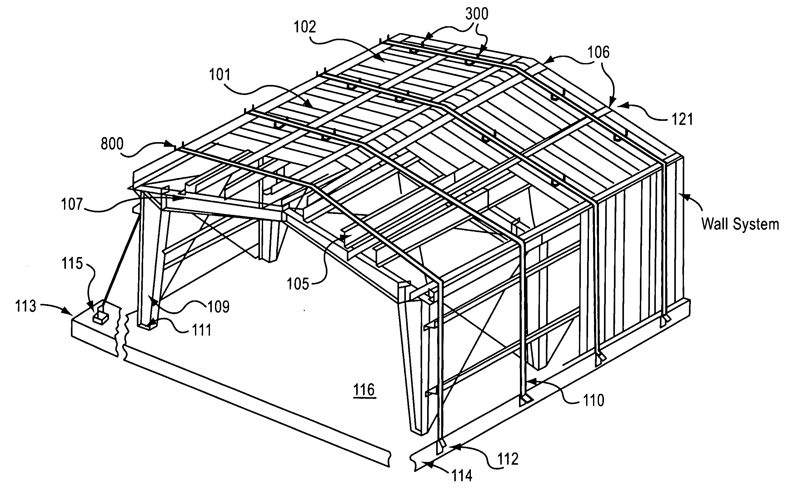
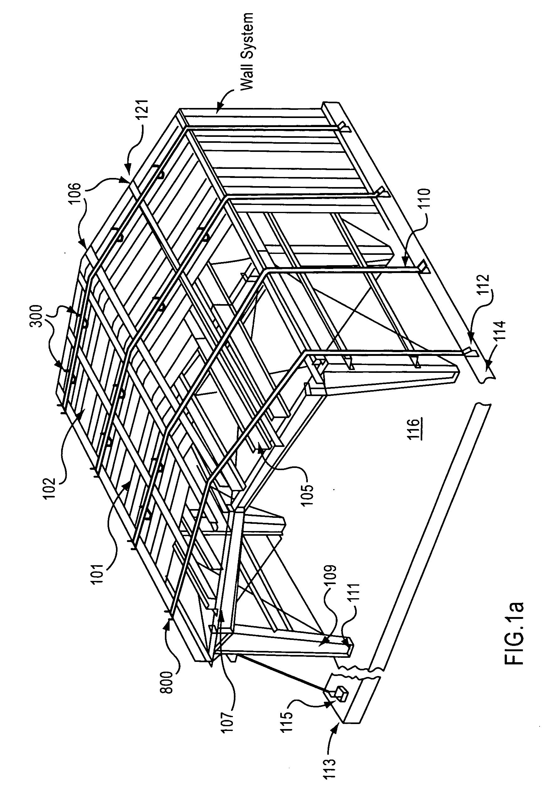
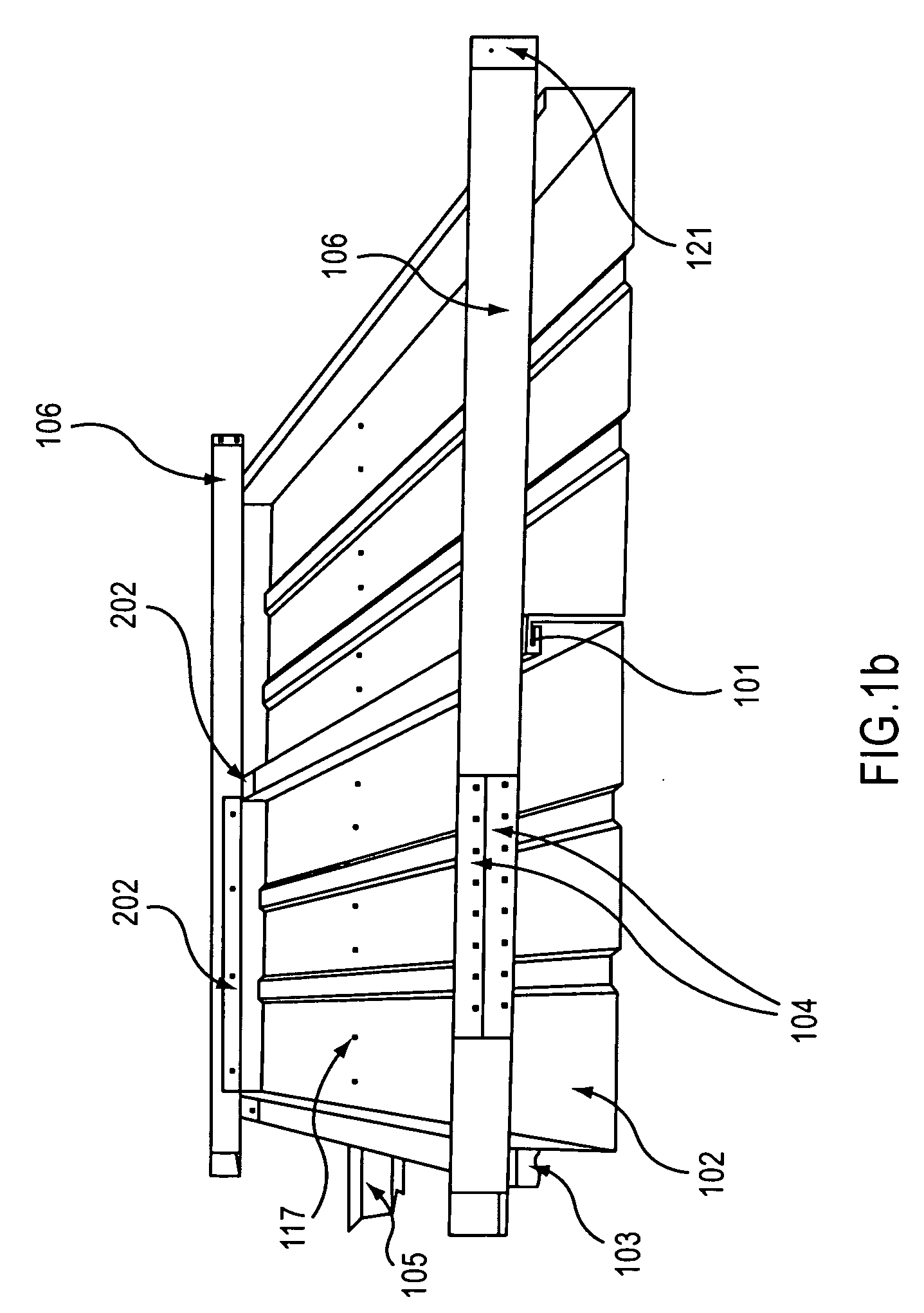
[0008]An embodiment of the present invention is directed to a strapping system including a roof assembly. The roof assembly includes a plurality of receiving channels, each of the plurality of receiving channels being fastened to interconnected roof materials connected to a roof structure. The roof assembly also includes a plurality of roof channels that are connected by the plurality of receiving channels and fastened to the interconnected roof materials, such that a row of interconnected roof channels and receiving channels is placed over the interconnected roof materials along a length of a roof structure. The strapping assembly also includes a plurality of straps for tying down the roof assembly to a corresponding plurality of anchors, each of the plurality of anchors being secured at predetermined distances at opposite sides of a foundation of a building. The strapping assembly further includes a plurality of tensioning devices mounted, at predetermined distances, on the roof materials between rows of interconnected roof channels and receiving channels, the plurality of tensioning devices being for eliminating vertical displacement of the fastened straps. Each of the plurality of straps is placed at a predetermined distance along the length of the roof structure over rows of interconnected roof channels and receiving channels and is threaded in a corresponding tensioning device that is lined up with a corresponding anchor at the foundation of the building. On opposite sides of the building, each of the plurality of straps is fastened to a corresponding ratchet assembly attached to a corresponding anchor of the plurality of anchors, thereby transferring load from the roof assembly to the foundation of the structure during a wind storm.
[0010]Another embodiment of the invention is directed to a method including fastening a plurality of receiving channels to interconnected roof materials connected to a roof structure. The method also includes connecting a plurality of roof channels to the plurality of receiving channels and fastening the connected plurality of roof channels to the interconnected roof materials. The method further includes placing a row of interconnected roof channels and receiving channels over the interconnected roof materials along a length of a roof structure. The method also includes securing a plurality of anchors at predetermined distances at opposite sides of a foundation of a building and mounting a plurality of tensioning devices, at predetermined distances, on the roof materials between rows of interconnected roof channels and receiving channels, the plurality of tensioning devices being for eliminating vertical displacement of the fastened straps. The method also includes placing each of a plurality of straps at a predetermined distance along the length of the roof structure over rows of interconnected roof channels and receiving channels, threading each of the plurality of straps in a corresponding tensioning device that is lined up with a corresponding anchor at the foundation of the building, and on opposite sides of the building, fastening each of the plurality of straps to a corresponding ratchet assembly attached to a corresponding anchor, thereby transferring load from the roof assembly to the foundation of the structure during a wind storm.

Problems solved by technology

When a metal pan roof system is exposed to extreme winds, such as hurricanes or tornadoes, un-repairable damage is likely to occur when fasteners attaching the metal roof panels to the structural frame fail.
The fasteners typically fail under pressure differentials (lift) created by airfoil (vacuum), as a consequence of high velocity winds over the surface of the roof compounded by high velocity of winds entering the structure.
This causes wind capture which is the development of an internal pressure to the underside of the roof panels.
There is currently no system for tying down roof structures with individual interconnected roof materials.
Due to the lack of appropriate systems for strapping down these roof structures, insurance companies typically hesitate to insure buildings with individual interconnected roof materials.

Method used


Image

  • Apparatus and method for securing a roof assembly during a severe wind storm
  • Apparatus and method for securing a roof assembly during a severe wind storm
  • Apparatus and method for securing a roof assembly during a severe wind storm

Examples


Embodiment Construction

[0025]Reference will now be made to the preferred embodiments of the present invention, examples of which are illustrated in the accompanying drawings.

[0026]The present invention provides a method for strengthening a roof with, for example, aluminium channels, which may be permanently or temporarily placed at the eaves, mid span, and ridge of the building. The roof is able to accept an extremely strong, low stretch strapping system which is installed over the channelling system and threaded into ratchets fastened to the foundation of the building and tightened. The building's entire roof assembly is, therefore, provided a positive downward load disbursement, which passes through the tie-down assembly directly to the foundation of the building.

[0027]FIG. 1a illustrates an embodiment of the present invention in which a plurality of tie-down straps 110 are tensioned between a corresponding plurality of anchors 112,115, secured at predetermined distances at opposites sides along a found...


PUM


Abstract

A strapping system includes a roof assembly including a plurality of receiving channels; each of the plurality of receiving channels is fastened to interconnected roof materials connected to a roof structure. The roof assembly also includes a plurality of roof channels that are connected by the plurality of receiving channels and fastened to the interconnected roof materials, such that a row of interconnected roof channels and receiving channels is placed over the interconnected roof materials along a length of a roof structure. The strapping assembly also includes a plurality of straps for tying down the roof assembly to a corresponding plurality of anchors, each of the plurality of anchors being secured at predetermined distances at opposite sides of a foundation of a building. The strapping assembly further includes a plurality of tensioning devices mounted, at predetermined distances, on the roof materials between rows of interconnected roof channels and receiving channels, the plurality of tensioning devices being for eliminating vertical displacement of the fastened straps. Each of the plurality of straps is placed at a predetermined distance along the length of the roof structure over rows of interconnected roof channels and receiving channels and is threaded in a corresponding tensioning device that is lined up with a corresponding anchor at the foundation of the building. On opposite sides of the building, each of the plurality of straps is fastened to a corresponding ratchet assembly attached to a corresponding anchor of the plurality of anchors, thereby transferring load from the roof assembly to the foundation of the structure during a high wind storm such as a, hurricane, typhoon, cyclone or a tornado.

Description

BACKGROUND OF THE INVENTION[0001]1. Field of the Invention[0002]The present invention relates to a system and method of tying down a roof structure of a building to prevent the roof structure from blowing off during a severe storm, and more particularly, to a system and method for strapping down a roof assembly such that uplift pressures to the roof assembly are transferred to the foundation of the building during a severe wind storm.[0003]2. Description of the Related Art[0004]During a storm with severe winds, such as a hurricane, a roof structure made of individual, interconnected roof materials is likely to detach from a building. Examples of such roof structures include metal pan roof structures on commercial / industrial buildings and roof structures on some residential buildings, such as mobile homes. For roof structures with individual, interconnected roof materials, such as metal pans, the bottom pan of each individual roof material is typically face screwed to the top of the ...

Claims


Application Information

Patent Timeline
IPC IPC(8): E04H9/14
CPCE04H9/14Y10S52/11Y10S52/12Y02A50/00
Inventor LOZIER, JAMESLOZIER, MAURICELOZIER, RITA
Owner HURRICANE HARNESS CORP
Learn More