Shaft connecting device for a heald shaft

a technology of connecting device and shaft, which is applied in the direction of cam shedding mechanism, loom, textiles and paper, etc., can solve the problem of inability to adjust the height of the shaft from the top, and achieve the effect of reliable transmission of for

Inactive Publication Date: 2009-01-01
GROZ BECKERT KG
View PDF13 Cites 6 Cited by
  • Summary
  • Abstract
  • Description
  • Claims
  • Application Information

AI Technical Summary

Benefits of technology

[0021]It is also possible to provide the lateral support and the thrust rod with meshing teeth. Thus, the clamping device achieves a positive-locking connection between the thr

Problems solved by technology

A height adjustment of shaft

Method used


Image

  • Shaft connecting device for a heald shaft
  • Shaft connecting device for a heald shaft
  • Shaft connecting device for a heald shaft

Examples


Embodiment Construction

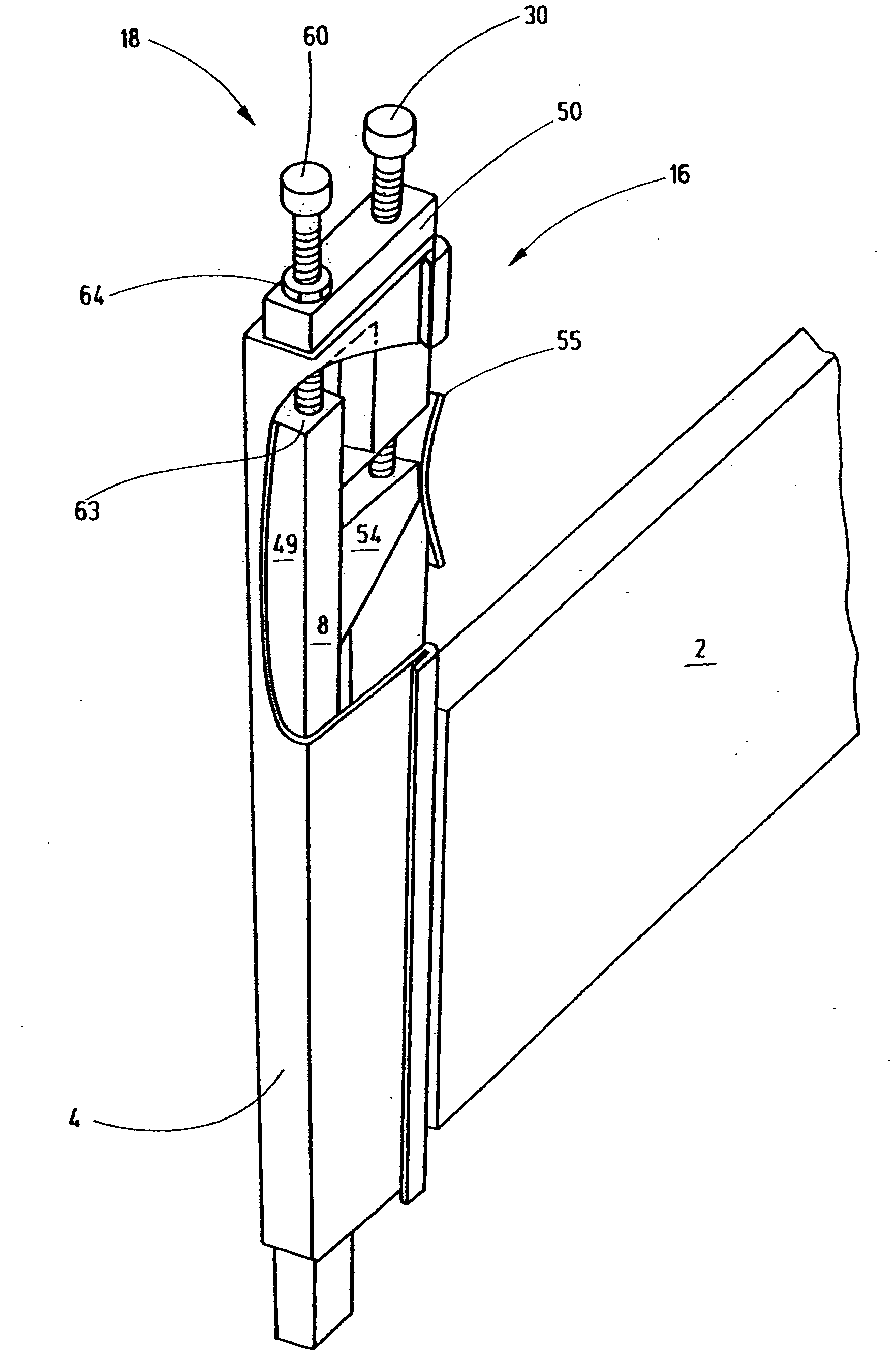
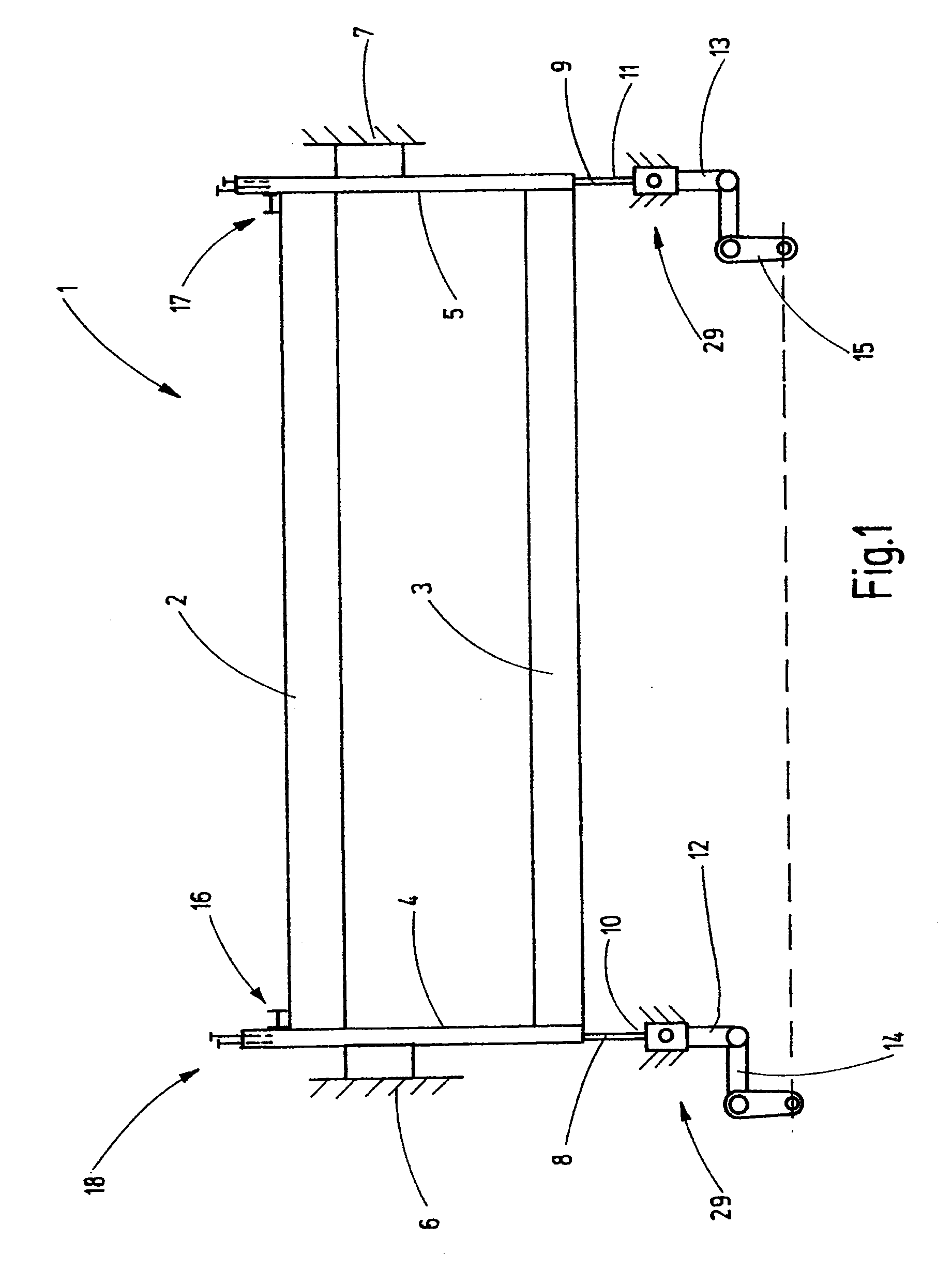
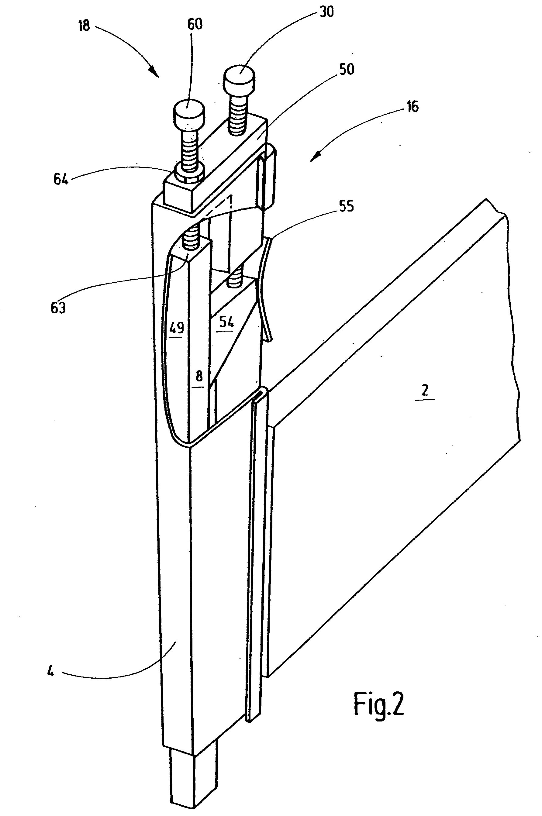
[0048]FIG. 1 shows a heald shaft built into a weaving machine, said shaft being associated with an upper shaft rod 2 that is arranged horizontally during operation, with a lower shaft rod 3 arranged parallel at a distance from said latter rod, and with two lateral supports 4, 5 that connect the ends of the shaft rods 2, 3 to each other. Heald support rails are held on the shaft rods 2, 3, whereby vertically arranged healds extend between said support rails during operation.

[0049]The heald shaft 1 is supported so that it can be vertically shifted in appropriate guides 6, 7. The guides 6, 7 may be, e.g., sliding guides which support the lateral supports 4, 5, so that they can be shifted. The lateral supports 4, 5 are configured, e.g., as hollow profiles. Thrust rods 8, 9 extend through said profiles' interior spaces, whereby said thrust rods are driven on their lower ends 10, 11 in vertical direction, i.e., they oscillate up and down. To achieve this in the present exemplary embodimen...


PUM


Abstract

A shaft connecting device (18) that comprises a thrust rod (8) and a lateral support (4) that fit into each other with minimal transverse play. In addition, the shaft connecting device (18) comprises a clamping device (16) with a stop means (60, 60′, 66) and a fixation means (30, 30′), the latter connecting the lateral support (4) and the thrust rod (8) exclusively on their respective upper ends to each other. Any opening, closing and adjusting of the connections between the thrust rod (8) and the lateral support (4) is possible in a particularly simple and convenient manner. The lateral support (4) and the thrust rod (8) support each other, thus resulting in a high dynamic load-bearing capacity. The overall design is simple, clear and cost-effective.

Description

CROSS-REFERENCE TO RELATED APPLICATION[0001]This application claims the priority of European Patent Application No. 07 012 444.1, filed Jun. 26, 2007, the subject matter of which, in its entirety, is incorporated herein by reference.BACKGROUND OF THE INVENTION[0002]The invention relates to a shaft connecting device for a heald shaft of a weaving machine.[0003]In most cases weaving machines comprise several heald shafts that are embodied by an essentially rectangular frame holding a large number of healds. The heald shafts usually have two shaft rods that are held horizontally during operation, said heald shafts being connected on their ends by vertically oriented lateral supports. These units are moved up and down in vertical direction by a shaft drive.[0004]Such a heald shaft is disclosed, e.g., by document U.S. Pat. No. 6,378,564 B1. In order to move the heald shaft in vertical direction, its two lateral supports are connected on their respective lateral ends to a thrust rod. To d...

Claims


Application Information

Patent Timeline
IPC IPC(8): D03C13/00D03D47/38
CPCD03C9/0683D03C9/065
Inventor GESING, KARL-HEINZBRUSKE, JOHANNES
Owner GROZ BECKERT KG
Why Eureka
Try Eureka