Turbo-machine for compressing gaseous or liquid fluid

A technology of turbines and compressors, which is applied to components of pumping devices for elastic fluids, liquid fuel engines, axial flow pumps, etc., and can solve problems such as the maximum allowable speed limit

Inactive Publication Date: 2014-05-07
ATLAS COPCO ENERGAS
View PDF6 Cites 0 Cited by
  • Summary
  • Abstract
  • Description
  • Claims
  • Application Information

AI Technical Summary

Problems solved by technology

However, the consequence of this is that stacking multiple blisks means that individual manufacturing and assembly tolerances accumulate, thus requiring a more robust and reliable bearing structure, and resulting in a limitation of the maximum allowable rotational speed

Method used


Image

  • Turbo-machine for compressing gaseous or liquid fluid
  • Turbo-machine for compressing gaseous or liquid fluid

Examples


Embodiment Construction

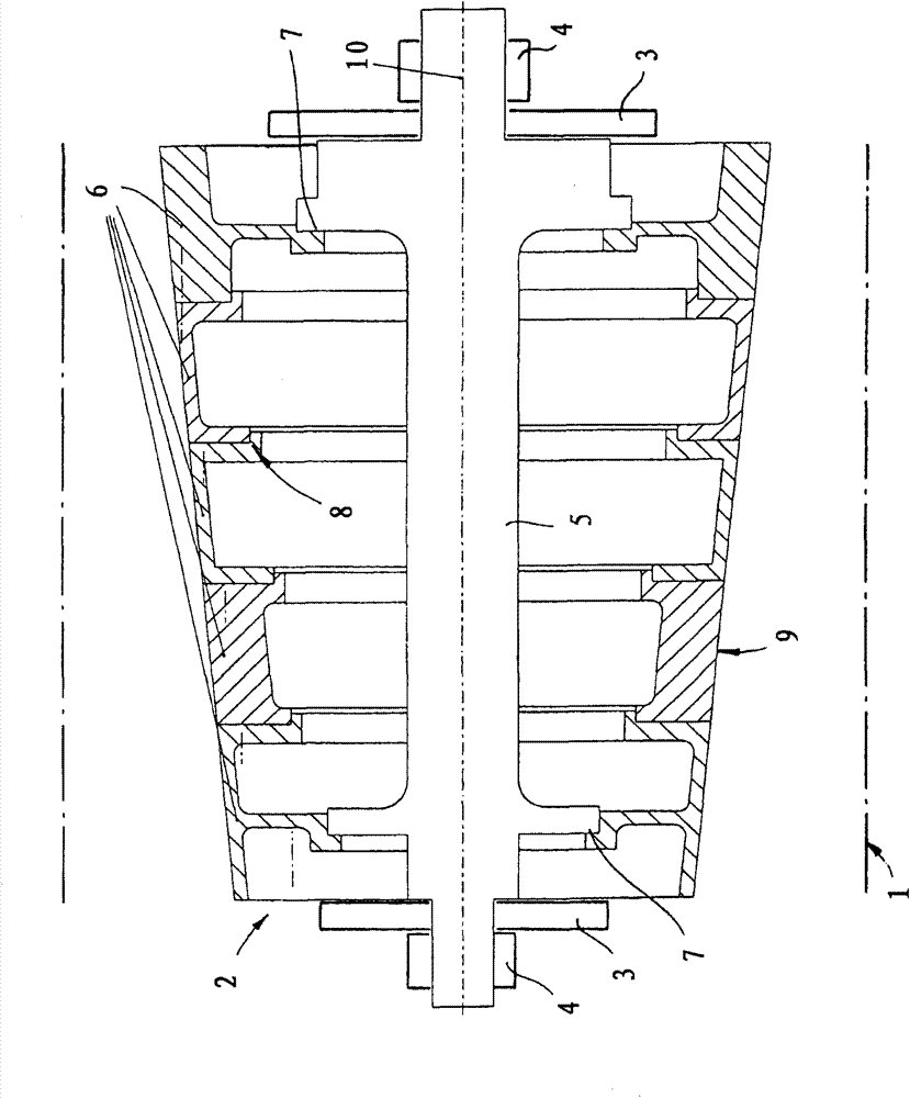
[0022] Such as figure 1 As shown, a turbine for compressing gas or vapor according to the invention has a housing 1 schematically indicated by dot-dash lines, and a rotor 2 rotatably supported in housing 1 on bearings 3 and 4 for rotation about an axis 10 . According to the invention, the rotor 2 has a shaft 5 of small diameter and a set of disks 6 a to 6 e with integrated rotor blades, one of which is schematically indicated at 14 . Two radially outwardly protruding bushes 7a and 7b are integrally formed on the shaft 5 and the rotor 2 is attached to the shaft 5 only at the position of the bushes. Only the two end discs 6a and 6e are fixed to respective bushings 7a and 7b. The shaft 5 is supported in the housing 1 via an axial magnetic bearing 3 and a radial magnetic bearing 4 .

[0023] The disks 6a to 6e of the rotor 2 are formed with stepped shoulders 8 forming radially facing annular surfaces and axially facing annular surfaces that complement each other, ensuring that s...


PUM


Abstract

A turbomachine for use as a compressor has a tubular housing centered on an axis, a rotor at least generally centered on the axis in the housing, and bearings supporting the rotor in the housing for rotation about the axis. The rotor is formed by a small-diameter shaft extending along and centered on the axis, formed with at least one mounting collar, and carried by the bearings, and by a plurality of annular disks fitted axially together and formed with radially outwardly extending vanes. At least one of the disks is fitted with and secured to the mounting collar.

Description

technical field [0001] The invention relates to a turbomachine. More particularly, the present invention relates to such machines for compressing fluids. Background technique [0002] A typical turbine has a stationary housing with a channel forming chamber extending along an axis and housing a rotor having a body supported by bearings for rotation about the axis. Axially extending vanes also project radially outward from the outer surface of the rotor body and compress the fluid as it flows axially through the housing. [0003] Turbines used in industrial applications such as chemical or petrochemical plants typically operate under precisely controllable conditions within a predetermined range of capacity and speed. The rotor is optimized for this operating point and is formed by a solid shaft to which the rotor blades are attached. Producing and balancing this type of rotor structure is expensive. For this purpose, fluid-lubricated bearing systems, such as oil-lubricat...

Claims


Application Information

Patent Timeline
Patent Type & Authority Applications(China)
IPC IPC(8): F04D19/00F04D29/053F04D29/056F04D29/32
CPCF04D29/0513F05D2240/50F04D29/266F05D2240/51F01D5/34F16C32/0489F01D25/22F04D29/644F04D29/057F16C32/06F01D5/022F05D2240/53Y02T50/671F16C32/0406F01D5/066F04D29/321F04D29/058Y02T50/60F04D19/04F04D29/04
Inventor S·博森A·佐佩尔H·维蒂希F·维贝
Owner ATLAS COPCO ENERGAS
Why Eureka
Try Eureka