Vehicle body rear structure

a rear structure and vehicle body technology, applied in the direction of roofs, transportation and packaging, vehicle arrangements, etc., can solve the problems of insufficient collision energy absorption upon rear-end collision, insufficient vehicle body rear structure described above, and difficulty in effectively dispersing input load from the receiving bracket, etc., to achieve excellent collision energy absorption performance and reduce weight and manufacturing cost.

Inactive Publication Date: 2009-01-01
HONDA MOTOR CO LTD
View PDF7 Cites 31 Cited by
  • Summary
  • Abstract
  • Description
  • Claims
  • Application Information

AI Technical Summary

Benefits of technology

[0016]According to a first aspect of the present invention, there is provided a vehicle body rear structure, which includes: a rear frame disposed on each side of a vehicle body; and a tank lower frame disposed beneath the rear frame and on the each side of the vehicle body, wherein the rear frame has a load-displacement characteristic having a ratio F / S of load F to displacement S larger than the ratio F / S of the tank lower frame, wherein a cross sectional deformation of the tank lower frame is suppressed so that the load does not rapidly decrease after reaching a maximum of a bending strength.
[0019]Therefore, the vehicle body rear structure described above can bear a large load input upon a rear-end collision, compared with the vehicle body rear structure provided with the conventional stiffening member
[0021]Accordingly, reductions in weight and manufacturing cost can be achieved in the vehicle body rear structure described above.
[0023]According to the vehicle body rear structure described above, the cross sectional deformation of the tank lower frame can be suppressed with a simple structure.
[0024]In addition, in the vehicle body rear structure described above, the tank lower frame may be made of a hollow member, and the cross sectional deformation may be suppressed by disposing at least one of a rib, a plate, and a filler inside the tank lower frame.
[0033]The vehicle body rear structure according to the present invention can bear a large load upon a rear-end collision and has an excellent collision energy absorption performance, in addition to enabling reductions in weight and manufacturing cost of the vehicle body rear structure.

Problems solved by technology

As a result, in the conventional vehicle body rear structure described above, it has been difficult to effectively disperse the input load from the receiving bracket 110 to the tension-compression bars 101 and side sills 105 via the tension-compression bars 101.
Therefore, the vehicle body rear structure described above can not sufficiently bear the large load input upon the rear-end collision.
As a result, in the vehicle body rear structure, uncrushed portions are left in these stiffening members, thereby resulting in insufficient collision energy absorption upon the rear-end collision.
As a result, in the vehicle body rear structure, a weight and manufacturing cost of the vehicle body rear structure are increased.

Method used


Image

  • Vehicle body rear structure
  • Vehicle body rear structure
  • Vehicle body rear structure

Examples


Embodiment Construction

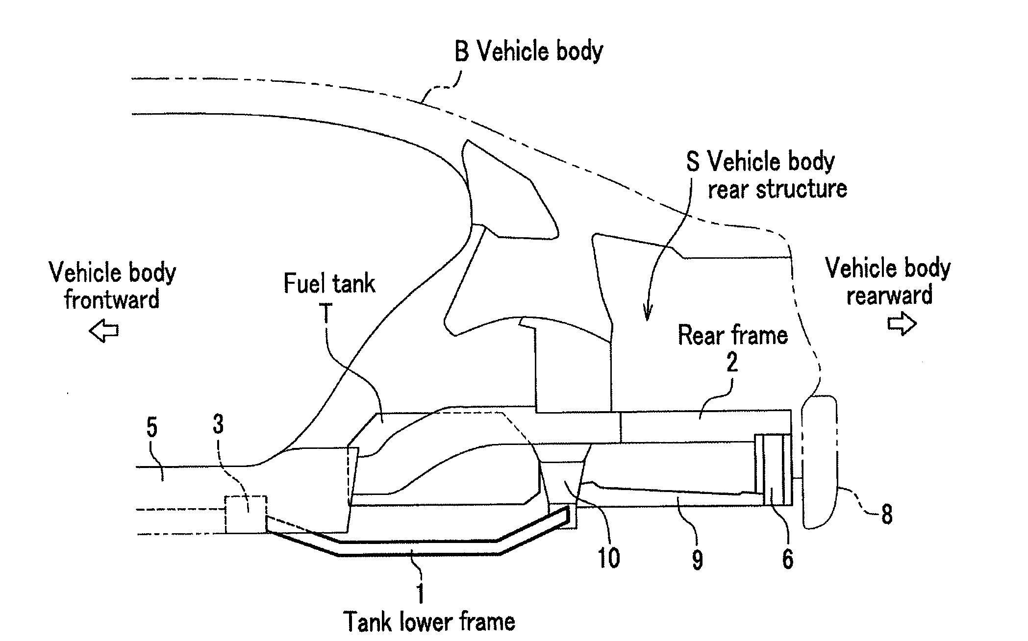
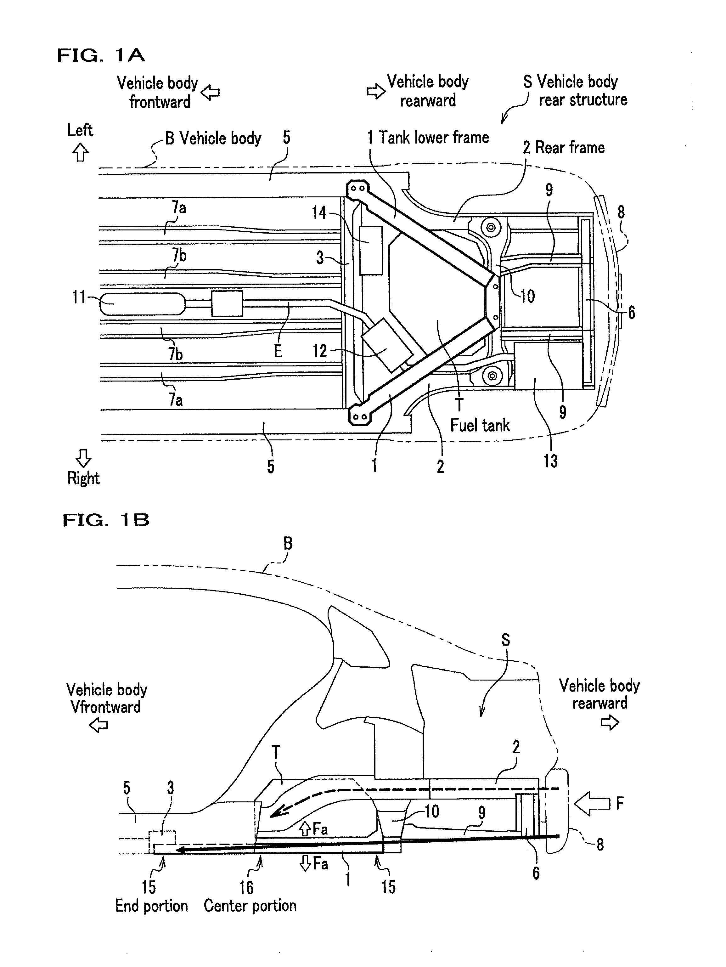
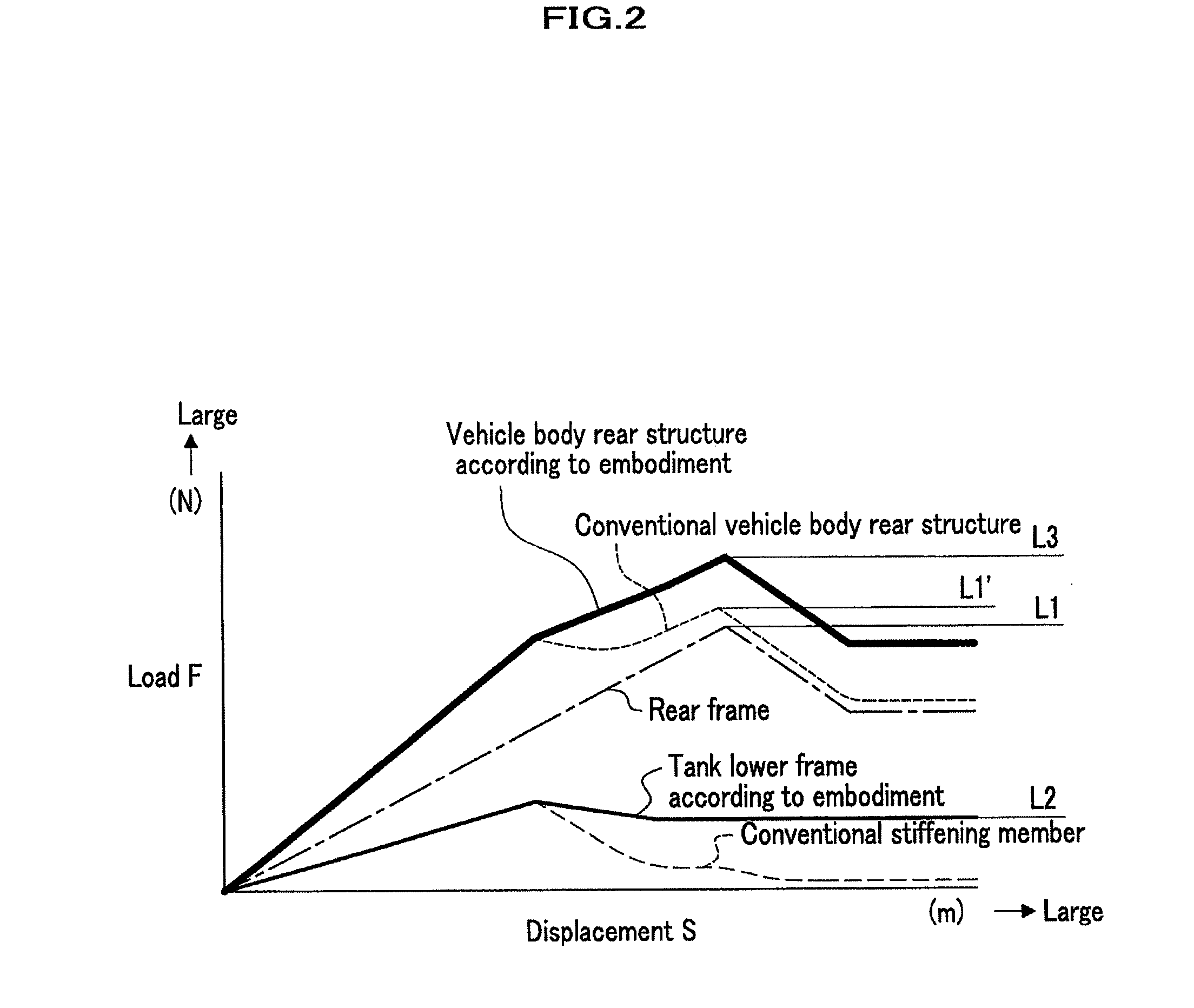
[0057]Next, a vehicle body rear structure according to embodiments of the present invention will be explained in detail by referring to drawings as needed. FIG. 1A is a bottom plane view schematically showing a vehicle body structure including a vehicle body rear structure according to an embodiment. FIG. 1B is a side view schematically showing the vehicle body rear structure according to the embodiment. FIG. 2 is a graph showing a load-displacement characteristic of a vehicle body rear structure according to the embodiment. FIG. 3A is a cross sectional view of a tank lower frame used for a vehicle body rear structure according to the embodiment. FIG. 3B to FIG. 3H are cross sectional views showing modified samples of the tank lower frame.

[0058]It is noted that the cross sectional views shown in FIG. 3A to FIG. 3H show cross sections perpendicular to neutral axes of the tank lower frames. In addition, in the explanations hereinafter, directions of left, right, top and bottom are bas...


PUM


Abstract

A vehicle body rear structure, which includes a rear frame disposed on each side of a vehicle body, and a tank lower frame disposed beneath the rear frame and on the each side of the vehicle body. The rear frame has a load-displacement characteristic having a ratio F / S of load F to displacement S larger than the ratio F / S of the tank lower frame, A cross sectional deformation of the tank lower frame is suppressed so that the load does not rapidly decrease after reaching a maximum of a bending strength.

Description

CROSS REFERENCE TO RELATED APPLICATIONS[0001]This application claims the foreign priority benefit under Title 35, United States Code, §119(a)-(d) of Japanese Patent Application No. 2007-010055, filed on Jan. 19, 2007, the contents of which are hereby incorporated by reference.BACKGROUND OF THE INVENTION[0002]1. Field of the Invention[0003]The present invention relates to a vehicle body rear structure.[0004]2. Description of Related Art[0005]Conventionally, a vehicle body rear structure provided with approximately a Y-shaped stiffening structure in plane view has been known. This is disclosed in, for example, U.S. Pat. No. 6,834,910. FIG. 11A is a bottom plane view schematically showing a conventional vehicle body rear structure as seen from a bottom side of a vehicle body. FIG. 11B is a side view schematically showing a conventional vehicle body rear structure as seen from a side of the vehicle body.[0006]As shown in FIG. 11A, the stiffening structure is formed in approximately the ...

Claims


Application Information

Patent Timeline
Patent Type & Authority Applications(United States)
IPC IPC(8): B60R27/00
CPCB60K15/063B62D25/087B62D21/152
Inventor YAMAGUCHI, TOSHIZUMIKAWABE, SATORUTSUYUZAKI, TAKUMI
Owner HONDA MOTOR CO LTD
Why Eureka
Try Eureka