MEMS device with bi-directional element

a technology of mechanical devices and components, applied in the direction of protective switch operating/release mechanisms, protective switch details, etc., can solve the problems of conventional microelectromechanical devices not meeting the needs of the telecom industry, and the switch or relay of microelectromechanical devices can be rendered unusable over tim

Inactive Publication Date: 2009-01-01
ALCATEL-LUCENT USA INC +1
View PDF15 Cites 7 Cited by
  • Summary
  • Abstract
  • Description
  • Claims
  • Application Information

AI Technical Summary

Problems solved by technology

If the deformation caused by mechanical creep is great enough, such as found from extended closures of a microelectromechanical switch or relay, the microelectromechanical switch or relay can be rendered unusable over time.
Given this requirement of the telecom industry and mechanical creep inherent in metal microelectromechanical switches and relays, conventional microelectromechanical devices may not meet the need of the telecom industry.

Method used


Image

  • MEMS device with bi-directional element
  • MEMS device with bi-directional element
  • MEMS device with bi-directional element

Examples


Embodiment Construction

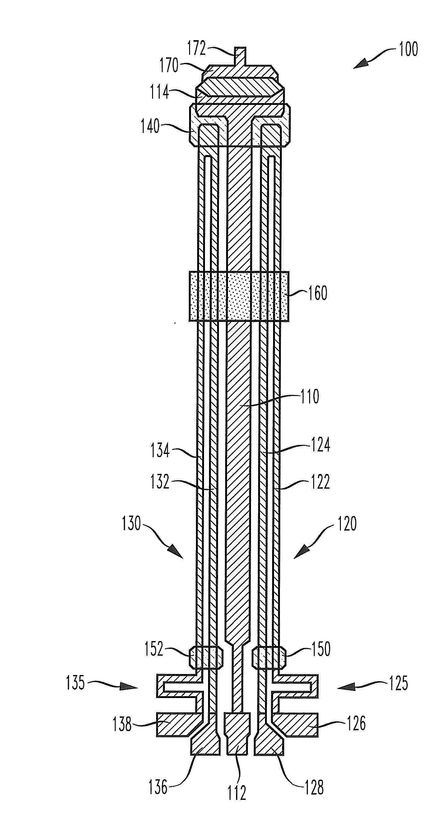
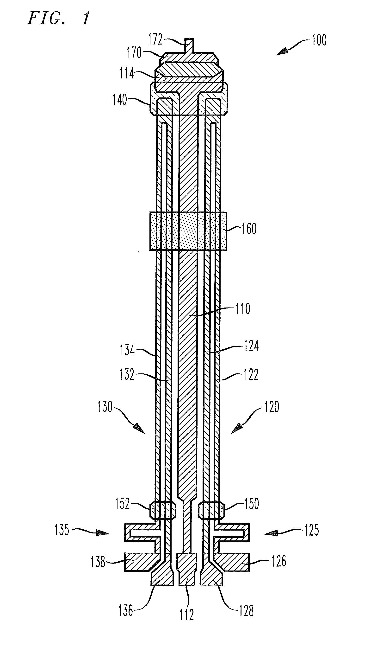
[0015]FIG. 1 illustrates a bi-directional microelectromechanical element 100 that contains a cold beam 110, a first beam pair 120, a second beam pair 130, and a free end tether 140. In some embodiments, the cold beam 110 can have a variable width, i.e., a tapered beam or can have two or more sections with different widths. The cold beam 110 has a first end connected to a cold beam anchor 112 and a free end 114. The free end 114 of the cold beam 110 is attached by conventional means to free end tether 140. The cold beam anchor 112 is attached by conventional means to a substrate (not shown). The cold beam 110 is typically made of a metal such as nickel. A portion of the bi-directional microelectromechanical element 100 is located over a trench in the substrate (not shown).

[0016]The first beam pair 120 is parallel to the cold beam 110 and is comprised of two parallel members, a first beam member 122 and a second beam member 124, each having a first and second end. The first end of eac...


PUM


Abstract

The present invention provides a bi-directional microelectromechanical element, a microelectromechanical switch including the bi-directional element, and a method to reduce mechanical creep in the bi-directional element. In one embodiment, the bi-directional microelectromechanical element includes a cold beam having a free end and a first end connected to a cold beam anchor. The cold beam anchor is attached to a substrate. A first beam pair is coupled to the cold beam by a free end tether and is configured to elongate when heated thereby to a greater temperature than a temperature of the cold beam. A second beam pair is located on an opposing side of the cold beam from the first beam pair and is coupled to the first beam pair and the cold beam by the free end tether. The second beam pair is configured to elongate when heated thereby to the greater temperature.

Description

TECHNICAL FIELD OF THE INVENTION[0001]The present invention is directed, in general, to a microelectromechanical device and, more specifically, to a microelectromechanical device, such as a switch or relay, with a bi-directional microelectromechanical element.BACKGROUND OF THE INVENTION[0002]Microelectromechanical devices, such as switches or relays, may be used as alternatives for conventional electromechanical devices. Advantages to microelectromechanical devices built using conventional semiconductor processes are programmability and reduced size, enabling smaller form factors and a corresponding reduction in power consumption, response time, and cost.[0003]One application that uses conventional microelectromechanical switches and relays is telecom switching gear. In these applications, a microelectromechanical switch or relay may be engaged in one position for a time ranging from weeks to years. It is known that metals under external forces, as found in, for example, components ...

Claims


Application Information

Patent Timeline
Patent Type & Authority Applications(United States)
IPC IPC(8): H01H71/18H01H61/00
CPCB81B3/0024B81B2201/014B81B2201/031H01H1/0036H01H2061/008H01H2001/0047H01H2037/008H01H2061/006H01H37/00B81B3/00
Inventor GASPARYAN, ARMANGATES, II, JOHN VANATTASIMON, MARIA ELINA
Owner ALCATEL-LUCENT USA INC
Why Eureka
Try Eureka