Liquid discharging apparatus, liquid discharging method, and program

a technology of liquid discharging apparatus and liquid discharging method, which is applied in the direction of printing, other printing apparatus, etc., can solve the problems of short travel time and long travel tim

Active Publication Date: 2009-01-01
SEIKO EPSON CORP
View PDF2 Cites 16 Cited by
  • Summary
  • Abstract
  • Description
  • Claims
  • Application Information

AI Technical Summary

Benefits of technology

[0008]An advantage of some aspects of the invention is to maintain the amount of liquid droplets discharged.

Problems solved by technology

For example, in a case in which a flow amount of the ink in the supply path is large, the travel time is short.
Alternatively, in a case in which the flow amount of the ink in the supply path is small, the travel time is long.
A problem of the change in the amount of the ink droplets discharged from the head is not limited to printers that discharge ink, and similarly occurs also in liquid discharging apparatuses that discharge liquid.

Method used


Image

  • Liquid discharging apparatus, liquid discharging method, and program
  • Liquid discharging apparatus, liquid discharging method, and program
  • Liquid discharging apparatus, liquid discharging method, and program

Examples


first embodiment

Advantages of First Embodiment

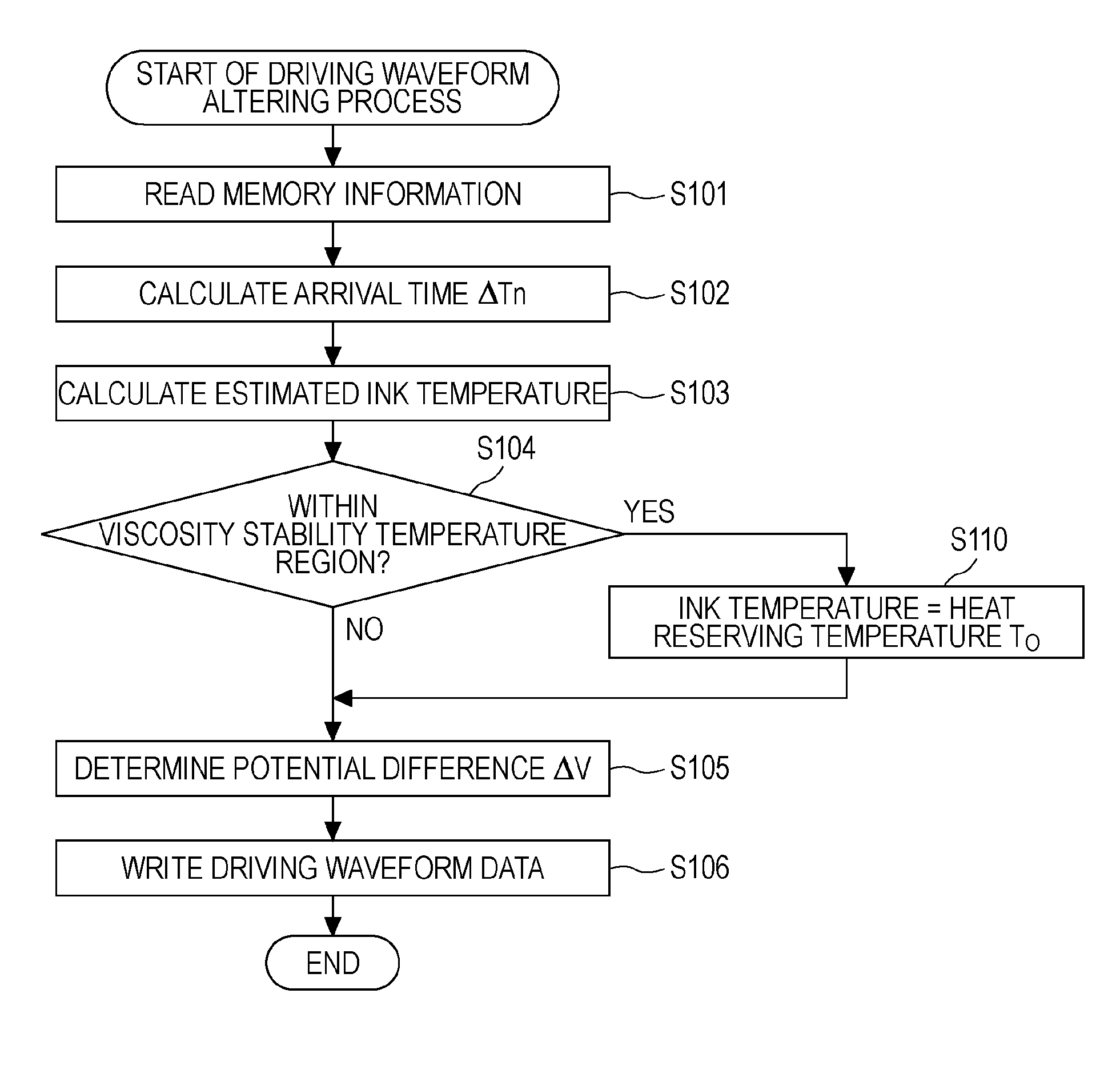
[0159]As described above with reference to FIGS. 8 to 12, in the first embodiment, the main controller 120 creates flow amount data, calculates a travel time Δtn from the flow amount data, calculates an estimated temperature T(Δtn) from the travel time Δtn, and determines a potential difference ΔV from the estimated temperature T(Δtn). After that, the main controller 120 writes, in the memory 122, driving waveform data representing all potential change points including a potential change point according to the determined potential difference ΔV. Subsequently, the driving signal generating circuit 124 generates a driving signal COM having a waveform corresponding to line segments connecting the potential change points represented by the driving waveform data, and inputs the driving signal COM to a head group of a corresponding color. In other words, in the first embodiment, the main controller 120 alters the driving waveform data in accordance with the f...

second embodiment

[0166]Next, a second embodiment of the invention will be described below with reference to FIGS. 14 to 15B. In the above-described first embodiment, the natural cooling after the ink arrives at the head case 140a is not considered. However, in the second embodiment, natural cooling of ink even in the head case 140a is considered. The configuration and components of a printing system according to the second embodiment are similar to those of the printing system 1 according to the first embodiment. Accordingly, by denoting them with identical reference numerals, their description is omitted.

[0167]FIG. 14 illustrates a supply path of the black ink. The ink supply path is identical to that in the first embodiment.

[0168]The tube 170K shown in FIG. 14 includes a main tube 171K and four subtubes 172K1, 172K2, 172K3, and 172K4 (hereinafter referred to also as “subtubes 172K”). As shown in FIG. 14, there is one main tube 171K and four subtubes 172K. The main tube 171K and the four subtubes 1...

third embodiment

[0184]Next, a third embodiment of the invention will be described below. In the third embodiment, a flowmeter is used in order to create flow amount data. The configuration and components of a printing system according to the third embodiment are similar to those of the printing system 1 according to the first embodiment. Accordingly, by denoting them with identical reference numerals, their description is omitted.

[0185]The flowmeter 152K shown in FIG. 16 is formed of, for example, a contact sensor for detecting the volume of the ink pack 151K. As shown in FIG. 16, the flowmeter 152K includes a spring having one end fixed to one surface of internal walls 150a of the ink tank 150, and a plate member fixed to the other end of the spring. The flowmeter 152K is configured so that the plate member, which receives an extending force of the spring, presses ink, with the plate member touching the ink tank 150. The position of the plate member changes with the volume of the ink pack 151K.

[01...


PUM


Abstract

A liquid discharging apparatus includes a head that is driven in response to a driving signal to discharge liquid, a controller that drives the head by generating the driving signal, an adjustment unit that adjusts the temperature of the liquid, and a supply path that supplies the head with the liquid having the temperature adjusted by the adjustment unit. The controller alters the driving signal in accordance with a flow amount of the liquid, which flows in the supply path.

Description

BACKGROUND[0001]1. Technical Field[0002]The present invention relates to a liquid discharging apparatus, a liquid discharging method, and a program used therewith.[0003]2. Related Art[0004]Ink jet printers are known examples of liquid discharging apparatuses that discharge liquid. In a printer of this type, a head is supplied with ink, and the head is driven to discharge the ink.[0005]A technology in which, when the ink is supplied to the head, the ink is heated by using a heater to heat a supply path for supplying the ink to the head has been proposed (see, for example, JP-A-2006-281454).[0006]In a case in which the heater is installed at a position at a distance from the head, the ink heated by the heater naturally cools by the time it arrives at the head, and its temperature decreases. A manner in which the temperature of the ink decreases differs according to a natural cooling time. Thus, the temperature of the ink in the head differs according to a travel time (natural cooling ...

Claims


Application Information

Patent Timeline
Patent Type & Authority Applications(United States)
IPC IPC(8): B41J29/38
CPCB41J2/04563B41J2/04588B41J2/04581B41J2/04571
Inventor AZAMI, NOBUAKINUNOKAWA, HIROKAZU
Owner SEIKO EPSON CORP
Why Eureka
Try Eureka