Liquid crystal display device

a liquid crystal display and display device technology, applied in non-linear optics, instruments, optics, etc., can solve the problems of not being sufficiently discussed, the application of circular polarizers, and the viewing angle, and achieve the effect of wide viewing angl

Inactive Publication Date: 2009-01-01
JAPAN DISPLAY CENTRAL CO LTD
View PDF6 Cites 17 Cited by
  • Summary
  • Abstract
  • Description
  • Claims
  • Application Information

AI Technical Summary

Benefits of technology

[0009]The object of the present invention is to provide a transflective liquid crystal display device which can realize a wide viewing angle and to which an OCB mode is applied.

Problems solved by technology

At present, however, the optimization of a circular polarizer, which is applied in a case where an optical design peculiar to the OCB mode is made, has not sufficiently been discussed.
In particular, there is such a problem that a viewing angle, at which a high contrast ratio (e.g. CR=10:1, or more) is obtained when transmissive display is performed, is narrow.

Method used


Image

  • Liquid crystal display device
  • Liquid crystal display device
  • Liquid crystal display device

Examples


first embodiment

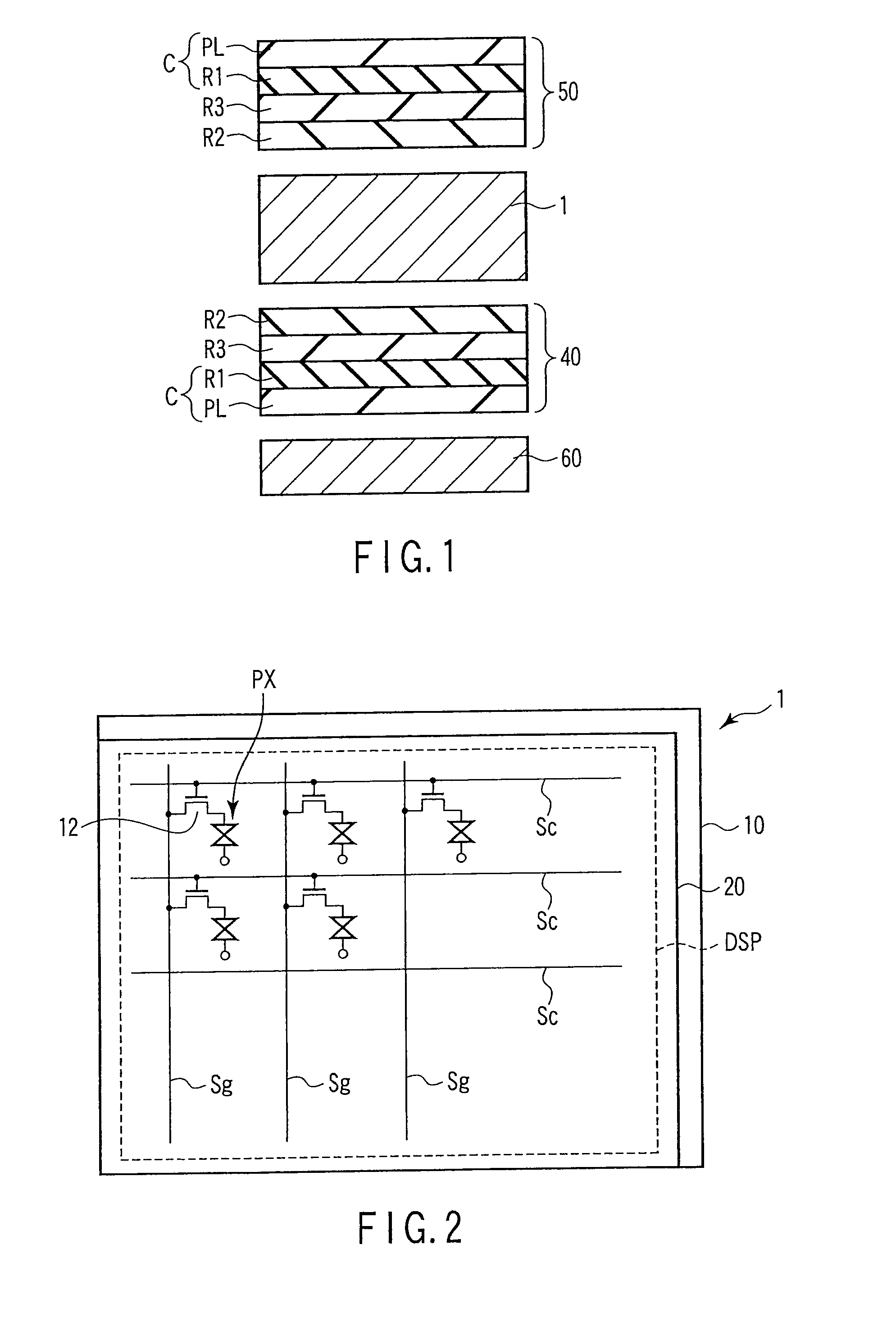
[0043]To begin with, a liquid crystal display device according to a first embodiment is described. In the first embodiment, the first optical element 40 and second optical element 50 have a function of optically compensating the retardation of the liquid crystal layer 30 in a predetermined display state in which a voltage is applied to the liquid crystal layer 30 in the above-described liquid crystal display panel 1. The first optical element 40 and second optical element 50 are configured to have retardation in their thickness direction.

[0044]As shown in FIG. 1, the first optical element 40 is disposed on the outer surface of the array substrate 10, and the second optical element 50 is disposed on the outer surface of the counter-substrate 20. The first optical element 40 and second optical element 50 have the same structure. Specifically, each of the first optical element 40 and second optical element 50 is configured to include a circular polarization element C including a polari...

second embodiment

[0061]Next, a liquid crystal display device according to a second embodiment is described. In the second embodiment, like the first embodiment, the first optical element 40 and second optical element 50 have a function of optically compensating the retardation of the liquid crystal layer 30 in a predetermined display state in which a voltage is applied to the liquid crystal layer 30 in the above-described liquid crystal display panel 1. In particular, in the second embodiment, the circular polarization element C, which is provided in one of the first optical element 40 and second optical element 50, includes a fourth retardation plate R4 which is disposed between the polarizer PL and the first retardation plate R1. Thus, the first optical element 40 and second optical element 50 are asymmetric with respect to the liquid crystal display panel 1.

[0062]In an example shown in FIG. 8, the circular polarization element C of the second optical element 50, which is disposed on the counter-s...

third embodiment

[0077]Next, a liquid crystal display device according to a third embodiment is described. In the third embodiment, the fourth retardation plate R4, which has biaxial refractive index anisotropy, is applied. Specifically, the fourth retardation plate R4 has refractive index anisotropy of nx>ny>nz. In the second optical element 50, the fourth retardation plate R4 is disposed between the polarizer PL and the first retardation plate R1 in such a manner that its slow axis is set at 0° azimuth. In short, the relationship between the slow axis of the fourth retardation plate R4 and the absorption axis of the polarizer PL is different from that in the second embodiment, and the fourth retardation plate R4 is disposed such that its slow axis is perpendicular to the absorption axis of the polarizer PL.

[0078]FIG. 11 shows a structure example of the third embodiment. The structure, other than the fourth retardation plate R4, is the same as the structure example of the second embodiment shown in...


PUM

PropertyMeasurementUnit
voltageaaaaaaaaaa
refractive index anisotropyaaaaaaaaaa
thicknessaaaaaaaaaa

Abstract

A liquid crystal display device having a reflective part and a transmissive part in each of a plurality of pixels which are arrayed in a matrix, includes a liquid crystal display panel which is configured such that a liquid crystal layer is held between a pair of substrates, and to which an OCB mode is applied, and a pair of optical elements which are disposed on outer surfaces of the liquid crystal display panel, respectively, and optically compensate a retardation of the liquid crystal layer in a predetermined display state in which a voltage is applied to the liquid crystal layer, wherein the optical element is configured to include a circular polarization element including a polarizer and a first retardation plate which is disposed between the polarizer and the liquid crystal display panel and imparts a retardation of 1/4 wavelength, and a second retardation plate which is disposed between the circular polarization element and the liquid crystal layer, and has refractive index anisotropy with a major axis being inclined to a normal line, and the optical element has a retardation in a thickness direction thereof.

Description

CROSS-REFERENCE TO RELATED APPLICATIONS[0001]This application is based upon and claims the benefit of priority from prior Japanese Patent Applications No. 2007-132836, filed May 18, 2007; No. 2007-132837, filed May 18, 2007; and No. 2008-125469, filed May 13, 2008, the entire contents of all of which are incorporated herein by reference.BACKGROUND OF THE INVENTION[0002]1. Field of the Invention[0003]The present invention relates to a liquid crystal display device, and more particularly to a transflective liquid crystal display device using an optically compensated bend (OCB) alignment technique which can realize an increase in viewing angle and an increase in response speed.[0004]2. Description of the Related Art[0005]Liquid crystal display devices have been applied to various fields by taking advantage of their features such as light weight, small thickness and low power consumption.[0006]In recent years, attention has been paid to a liquid crystal display, to which the OCB mode is...

Claims


Application Information

Patent Timeline
Patent Type & Authority Applications(United States)
IPC IPC(8): G02F1/1335
CPCG02F1/133371G02F1/133555G02F1/13363G02F1/13471G02F2001/133638G02F2413/14G02F2413/04G02F2413/105G02F2413/11G02F2413/12G02F2202/40G02F1/133634G02F1/133638
Inventor OKITA, MITSUTAKANISHIYAMA, KAZUHIROARAKI, SHIGESUMIHIGANO, EMI
Owner JAPAN DISPLAY CENTRAL CO LTD
Why Eureka
Try Eureka