Ultraviolet light-emitting diode exposure apparatus for microfabrication

a technology of ultraviolet light and exposure apparatus, applied in the field of light sources, can solve the problems of high cost of ownership, unwanted infrared radiation, and relatively short life of mercury lamps

Inactive Publication Date: 2009-01-01
OPTICAL ASSOCS
View PDF6 Cites 69 Cited by
  • Summary
  • Abstract
  • Description
  • Claims
  • Application Information

AI Technical Summary

Problems solved by technology

Various drawbacks are associated with the use of mercury lamps including environmental concerns, unwanted infrared radiation requiring filtering opt

Method used


Image

  • Ultraviolet light-emitting diode exposure apparatus for microfabrication
  • Ultraviolet light-emitting diode exposure apparatus for microfabrication
  • Ultraviolet light-emitting diode exposure apparatus for microfabrication

Examples


Embodiment Construction

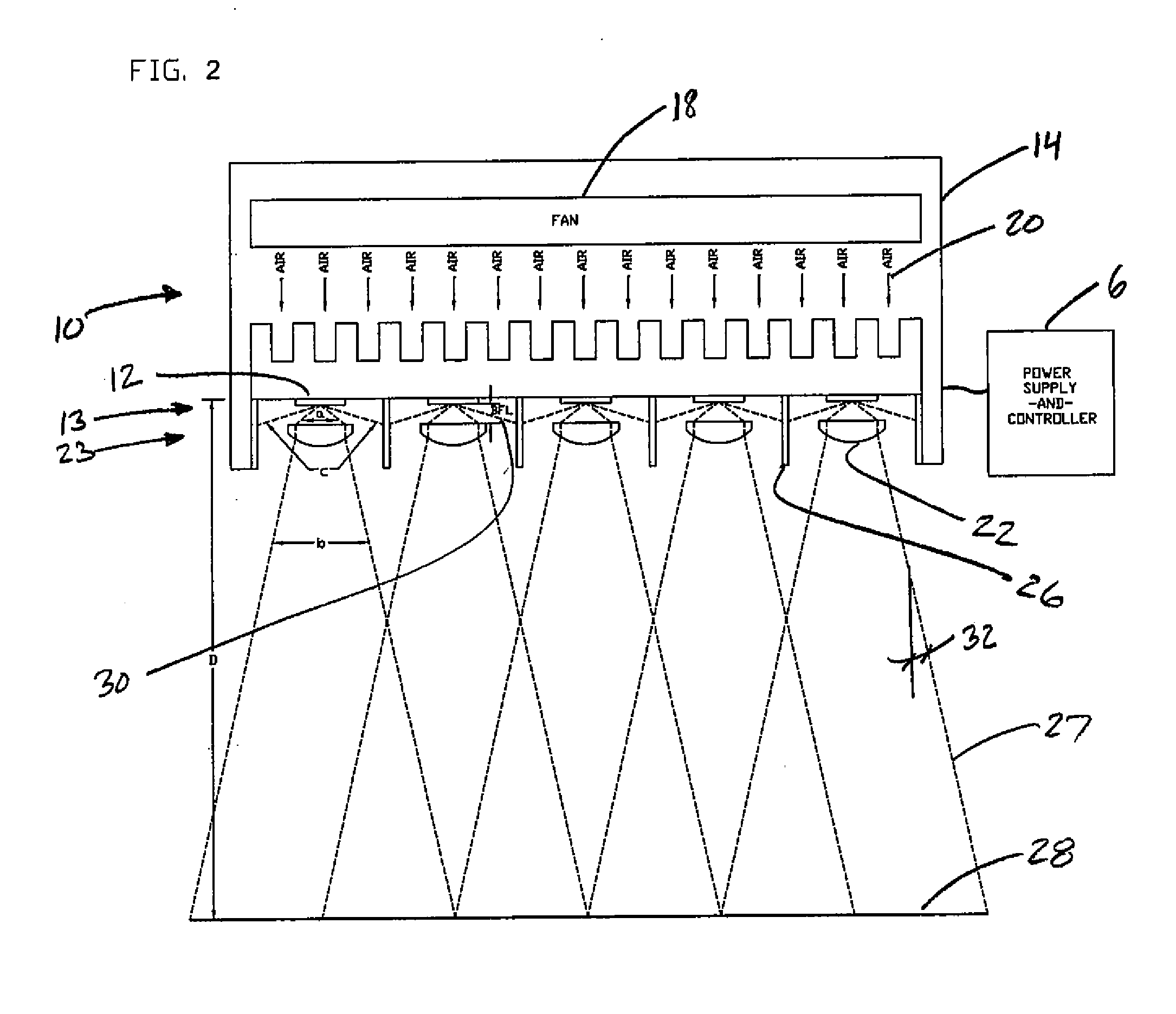
[0008]The exposure apparatus of the present invention is directed toward use in optical lithography. The exposure apparatus includes a light source that directs light through a collimating lens or lenses. In the optical lithography process, the light beams emitted from the light source are collimated by the lenses to a certain degree and are directed to an exposure plane. The exposure plane may include a substrate coated with a photoresist and may be masked to achieve a desired pattern.

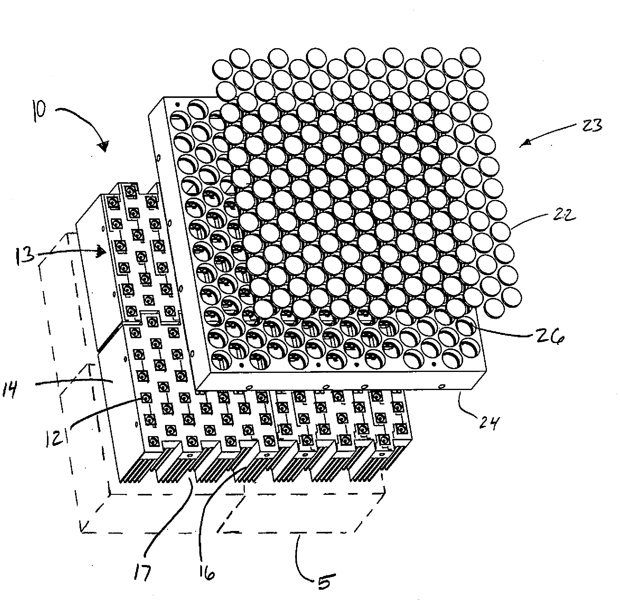
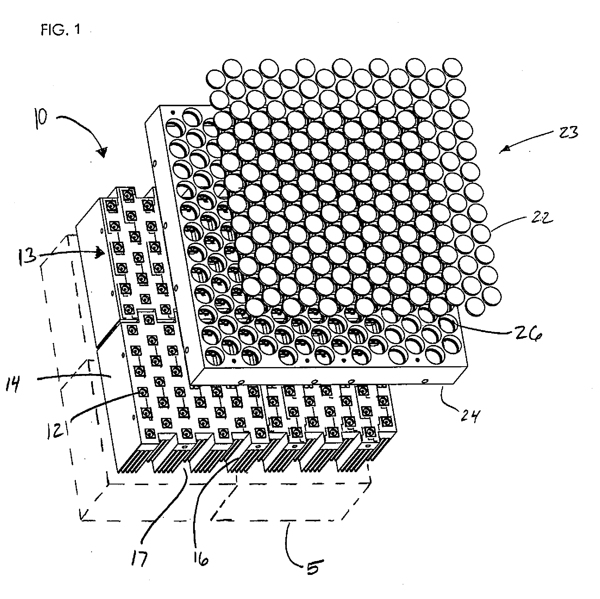
[0009]The exposure apparatus of the present invention may be carried by a frame 5 for positioning and orienting the exposure apparatus. The frame 5 may be further positioned within a mask aligner. In some embodiments, the frame 5 may be fixed. In other embodiments, the frame 5 may be moveable and yet fixable so as to be stationary during the exposure process.

[0010]The exposure apparatus includes a light source 10 comprising high-power UV-LED modules 12 arranged in an array 13 on a holder or holders 14...


PUM


Abstract

An exposure apparatus for use in optical lithography can include a holder and a plurality of UV-LED modules carried by the holder and disposed in an array. A respective plurality of collimating lenses can be disposed in an array corresponding to the array of UV-LED modules. The plurality of UV-LED modules and the respective plurality of collimating lenses can provide a respective plurality of distinct beams of UV light. The plurality of collimating lenses may be spaced from the plurality of UV-LED modules and spaced from the exposure plane and have an optical configuration providing a composite beam of UV light formed from the plurality of distinct beams of UV light in which each beam inside the periphery of the array overlaps each adjacent beam by at least 70% at the exposure plane. A method for directing light onto an exposure plane in an optical lithography procedure is provided.

Description

CROSS-REFERENCE TO RELATED APPLICATION[0001]The application claims priority to U.S. provisional patent application No. 60 / 937,757 filed on Jun. 29, 2007.FIELD OF THE INVENTION[0002]The present invention pertains to light sources and more particularly to light sources for optical lithography applications.BACKGROUND[0003]Optical lithography is a commonly used microfabrication processes. It is widely used in semiconductor chip manufacturing and microfluidics industries. Optical lithography involves exposing a substrate to a collimated uniform beam of light emanated from a light source and further developing the substrate thereby creating a pattern on the substrate. Various methods and approaches to optical lithography are known in the art which use a mercury lamp as a light source. See, for example, U.S. Pat. Nos. 4,024,428, 4,117,375, and RE30,571. Various drawbacks are associated with the use of mercury lamps including environmental concerns, unwanted infrared radiation requiring fil...

Claims


Application Information

Patent Timeline
IPC IPC(8): G03B27/32G03B27/54
CPCG03F7/70391G03F7/7005
Inventor LIU, RONGPALMER, EVAN
Owner OPTICAL ASSOCS
Why Eureka
Try Eureka