Optical information recording device, optical information recording method, optical information reproduction device and optical information reproduction method

a recording device and optical information technology, applied in the field of optical information recording devices, optical information recording methods, optical information reproduction devices and optical information reproduction methods, can solve the problems of taking time for the above optical disc devices, and the optical disc devices may not be able to increase recording and reproducing speed, so as to increase recording speed, increase reproducing speed, and increase recording speed

Inactive Publication Date: 2009-01-01
SONY CORP
View PDF9 Cites 28 Cited by
  • Summary
  • Abstract
  • Description
  • Claims
  • Application Information

AI Technical Summary

Benefits of technology

[0009]The present invention has been made in view of the above points and is intended to provide an optical information recording device, optical information recording method, optical information reproduction device and optical information reproduction method capable of increasing the recording and reproducing speed with the use of an optical beam.
[0016]According to an embodiment of the present invention, the recording marks can be at least formed on both surfaces of the optical information recording medium at the same time. Therefore, an optical information recording device and optical information recording method capable of increasing the recording speed with the use of an optical beam can be realized.
[0017]Moreover, by using the interference of the optical beams, the recording marks can be at least formed at two or more positions on the optical information recording medium at the same time. Therefore, an optical information recording device and optical information recording method capable of increasing the recording speed with the use of an optical beam can be realized.
[0018]Furthermore, the recording marks can be at least reproduced from both surfaces of the optical information recording medium at the same time. Therefore, an optical information reproduction device and optical information reproduction method capable of increasing the reproducing speed with the use of an optical beam can be realized.

Problems solved by technology

However, it takes time for the above optical disc device to form a hologram due to the chemical characteristics of the optical disc.
Moreover, since there is an upper limit on the rotation speed of the optical disc in terms of the axial run-out of the optical disc, the optical disc device may not be able to increase the recording and reproducing speed.

Method used


Image

  • Optical information recording device, optical information recording method, optical information reproduction device and optical information reproduction method
  • Optical information recording device, optical information recording method, optical information reproduction device and optical information reproduction method
  • Optical information recording device, optical information recording method, optical information reproduction device and optical information reproduction method

Examples


first embodiment

(1) First Embodiment

[0044]The following describes the configuration of an optical disc 100, or an optical information recording medium, according to a first embodiment of the present invention. How to record and reproduce information by using the optical disc 100 is also described below.

(1-1) Configuration of Optical Disc

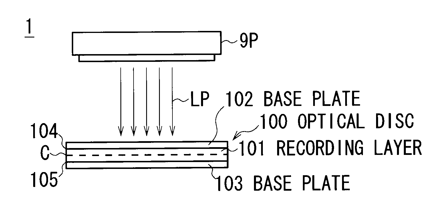
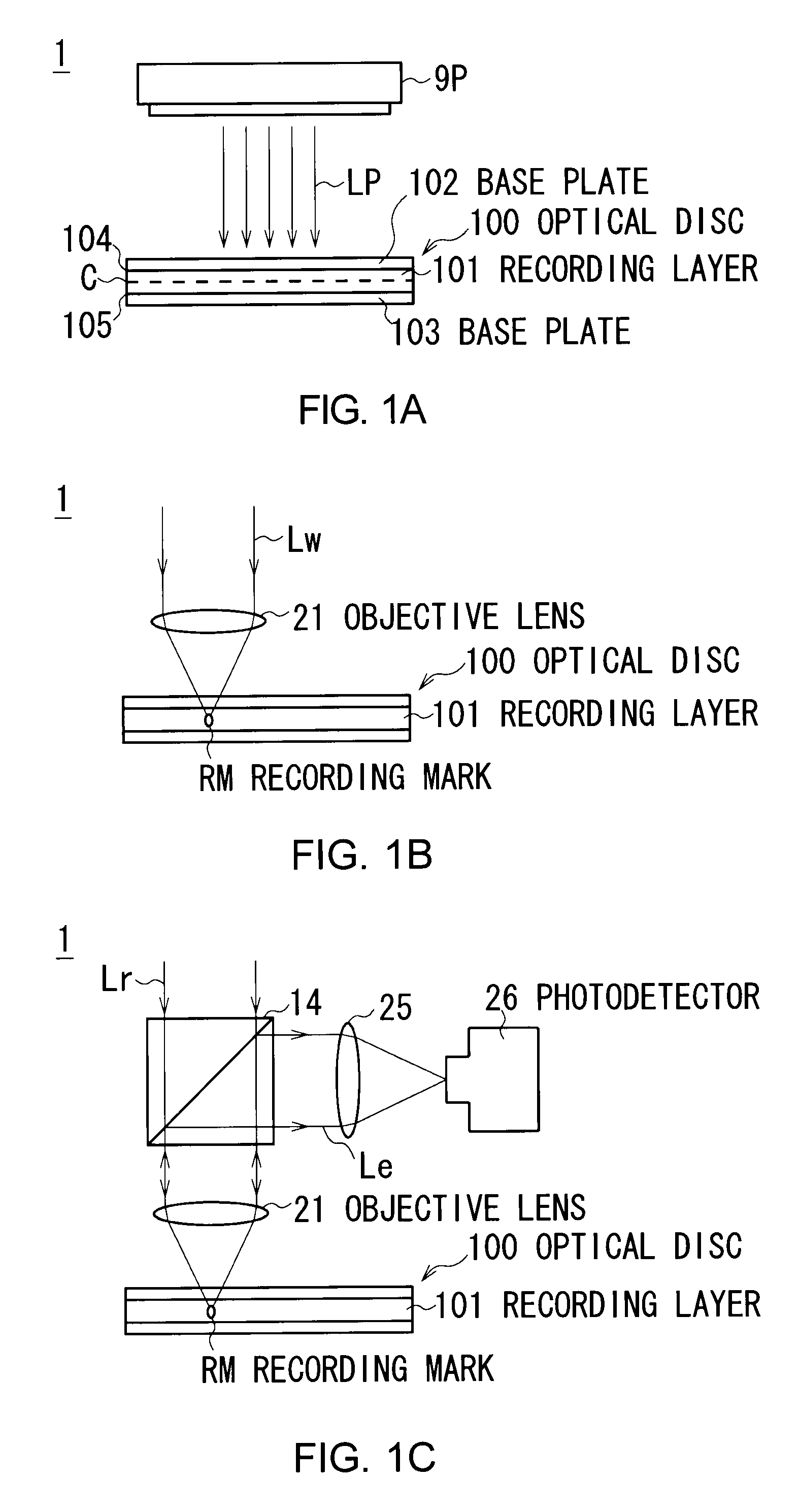
[0045]FIG. 1A is a side view of the optical disc 100. The optical disc 100 includes a flat recording layer 101 on which information are recorded. The recording layer 101 is sandwiched between a flat base plate 102 and a base plate 103. The optical disc 100 also includes reflection and transmission films 104 and 105 as positional reference layer: The reflection and transmission film 104 is positioned at a boundary between the base plate 102 and the recording layer 101 while the reflection and transmission film 105 is positioned at a boundary between the base plate 103 and the recording layer 101.

[0046]The recording layer 101 is made from photopolymerizable photopolym...

second embodiment

(2) Second Embodiment

(2-1) Basic Concept for Recording and Reproducing Information

[0109]A second embodiment of the present invention is different from the first embodiment. Information are recorded and reproduced from an optical disc 200, as shown in FIG. 6A.

[0110]The optical disc 200 is partly similar to the optical disc 100 (FIG. 1A). A recording layer 201 is sandwiched between a base plate 202 and a base plate 203. In addition, there is a reflection and transmission film 204 at a boundary between the recording layer 201 and the base plate 202. But there is no reflection and transmission film at a boundary between the recording layer 201 and the base plate 203.

[0111]The recording layer 201 is made from photopolymer or the like: It reacts to a blue optical beam with a wavelength of 405 nm, for example, and its refractive index changes according to the intensity of the beam.

[0112]In reality, the recording layer 201 of the optical disc 200 is previously formatted. The entire undersur...

third embodiment

(3) Third Embodiment

(3-1) Basic Concept for Recording and Reproducing Information

[0149]A third embodiment of the present invention is different from the first and second embodiments. Information are recorded and reproduced from an optical disc 300, as shown in FIG. 12A.

[0150]The optical disc 300 is partly similar to the optical disc 100 (FIG. 1A) and the optical disc 200 (FIG. 6A). A recording layer 301 is sandwiched between a base plate 302 and a base plate 303. In addition, there is a reflection and transmission film 304 at a boundary between the recording layer 301 and the base plate 302.

[0151]The recording layer 301 is made from photopolymer or the like: It reacts to a blue optical beam with a wavelength of 405 nm, for example, and its refractive index changes according to the intensity of the beam.

[0152]When the upper surface and undersurface of the recording layer 301 are exposed to the predetermined intensity of coherent recording optical beams Lw1 and Lw2 with a wavelength o...


PUM

PropertyMeasurementUnit
angleaaaaaaaaaa
wavelengthaaaaaaaaaa
reaction rateaaaaaaaaaa

Abstract

An optical information recording device includes: a section that acquires recording information that should be recorded on an optical information recording medium on which information are recorded by forming a recording mark at a position where an optical beam is focused on and from which the information are reproduced based on the reflectance of the recording mark; a section including at least one or more one-surface beam emission sections that emit a recording beam according to part of the recording information to one surface of the recording medium and focus the beam on a target position to form the recording mark; and an section including at least one or more other-surface beam emission sections that emit an recording beam according to the rest of the recording information to the other surface of the recording medium and focus the beam on a target position to form the recording mark.

Description

CROSS REFERENCES TO RELATED APPLICATIONS[0001]The present invention contains subject matter related to Japanese Patent Application JP2007-172904 filed in the Japanese Patent Office on Jun. 29, 2007, the entire contents of which being incorporated herein by reference.BACKGROUND OF THE INVENTION[0002]1. Field of the Invention[0003]The present invention relates to an optical information recording device, optical information recording method, optical information reproduction device and optical information reproduction method, and is preferably applied to an optical information recording and reproducing device that records information on a recording medium by using an optical beam and reproduces the information from the recording medium by using an optical beam, for example.[0004]2. Description of the Related Art[0005]As an optical information recording and reproducing device, an optical disc device is popular: The optical disc device uses a disc-shaped optical disc as an information rec...

Claims


Application Information

Patent Timeline
Patent Type & Authority Applications(United States)
IPC IPC(8): G11B7/00G11B7/24035G11B7/24044G11B7/249
CPCG11B7/0045G11B7/00452G11B2007/0009G11B7/14G11B7/0065
Inventor YAMATSU, HISAYUKI
Owner SONY CORP
Why Eureka
Try Eureka