
Method and system for a second order input intercept point (IIP2) correction

a second-order input and intercept point technology, applied in the field of radio signal processing, can solve the problems of significant degradation of the signal-to-noise ratio (snr) and/or bit-error-rate performance of gsm handsets, and many of the circuits and/or components utilized in the receiver or the transmitter may produce errors in generation

Inactive Publication Date: 2009-01-01
AVAGO TECH INT SALES PTE LTD
View PDF9 Cites 59 Cited by
  • Summary
  • Abstract
  • Description
  • Claims
  • Application Information

AI Technical Summary

Benefits of technology

This approach effectively corrects signal degradation and improves noise performance in RF receivers by compensating for DC offset voltages, enhancing the SNR and BER in RF transceivers across varying operational conditions.

Problems solved by technology

However, this gain level may vary significantly based on operational conditions, such as temperature and / or voltage supplies, or based on manufacturing conditions, such as the non-uniformity in transistor parameters that result from normal variations in the manufacturing process.
In systems based on the Global System for Mobile Communications (GSM) standard, for example, PVT variations in many of the circuits and / or components utilized in the receiver or the transmitter may produce errors in the generation of “I” (in-phase) and “Q” (quadrature) signal components.
These errors may result in a significant degradation in the signal-to-noise ratio (SNR) and / or the bit-error-rate (BER) performance of GSM handsets.

Method used


Image

  • Method and system for a second order input intercept point (IIP2) correction
  • Method and system for a second order input intercept point (IIP2) correction
  • Method and system for a second order input intercept point (IIP2) correction

Examples


Embodiment Construction

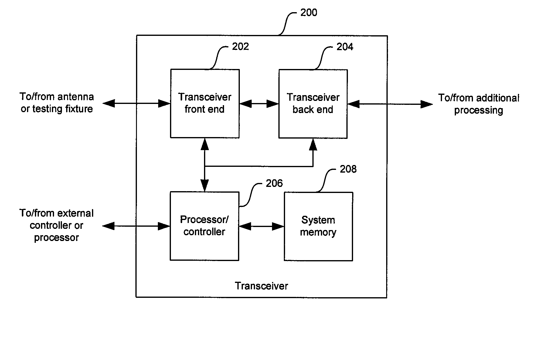
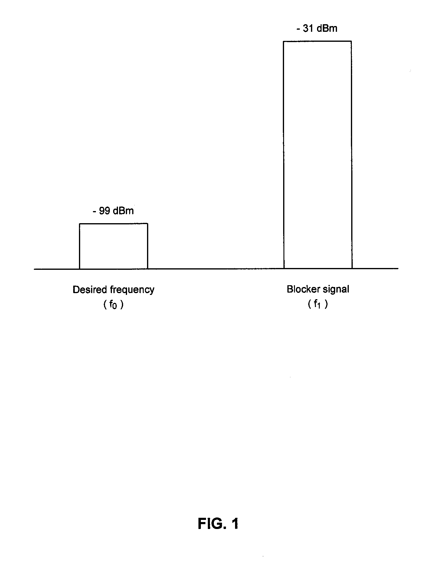
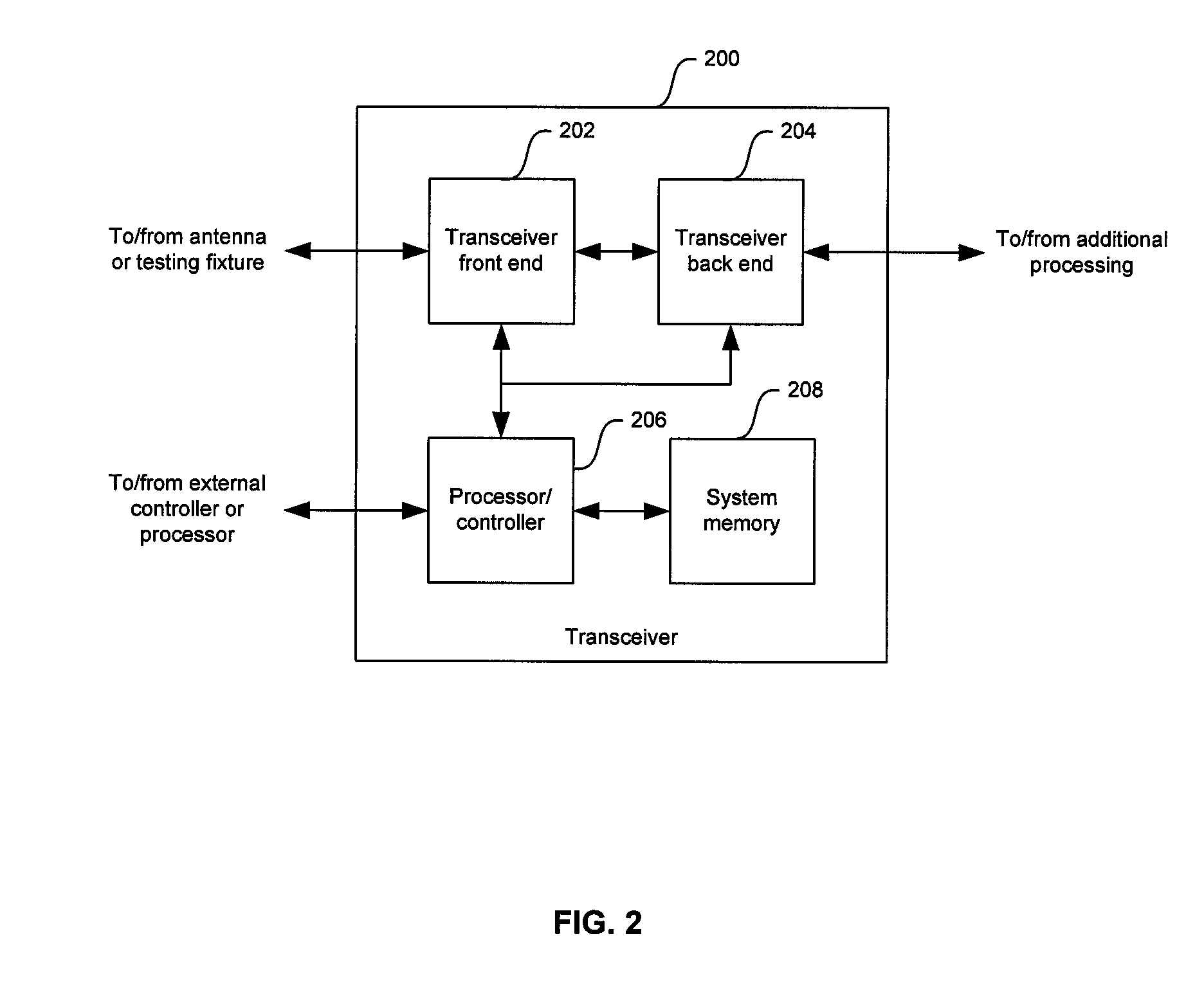
[0040]Certain embodiments of the invention may be found in a method and system for a second order input intercept point (IIP2) correction. By utilizing injection circuits in the signal components paths of an RF receiver, DC offset voltages resulting from second order nonlinearity effects on blocker signals may be corrected. The injection circuits may utilize information provided by a DC offset sensor to generate DC offset currents of the appropriate amplitude and polarity to correct the DC offset voltages. Moreover, the injection circuits may have the built-in capability to correct or adjust the gain in the injection circuits. This approach may provide a flexible and cost effective way to correct any signal saturation and / or noticeable degradation in an RF receiver's noise performance that may result from the DC offset voltages produced by the presence of interfering signals in the channel of interest.

[0041]FIG. 1 illustrates an exemplary desired signal and an exemplary blocker sign...


PUM


Abstract

In RF transceivers, a method and system for a second order input intercept point (IIP2) correction are provided. A DC offset sensor may detect DC offset voltages produced by blocker signals in “I” and “Q” signal component paths in an RF receiver. The DC offset sensor may generate control signals which may be utilized by a first and second injection circuits to generate DC offset currents that compensate for the DC offset voltages in the signal component paths. An injection circuit may utilize current drivers to generate binary weighted currents which may be added together to produce a DC offset current. The polarity of the DC offset current and the selection of which current drivers to use may be determined by the control signals. A calibration voltage may also be utilized to correct or adjust the gain in the injection circuit.

Description

CROSS-REFERENCE TO RELATED APPLICATIONS / INCORPORATION BY REFERENCE[0001]This application is related to the following applications, each of which is incorporated herein by reference in its entirety for all purposes:[0002]U.S. patent application Ser. No. ______ (Attorney Docket No. 16149US01) filed ______, 2004;[0003]U.S. patent application Ser. No. ______ (Attorney Docket No. 16150US01) filed ______, 2004;[0004]U.S. patent application Ser. No. ______ (Attorney Docket No. 16152US01) filed ______, 2004;[0005]U.S. patent application Ser. No. ______ (Attorney Docket No. 16153US01) filed ______, 2004;[0006]U.S. patent application Ser. No. ______ (Attorney Docket No. 16154US01) filed ______, 2004;[0007]U.S. patent application Ser. No. ______ (Attorney Docket No. 16155US01) filed ______, 2004;[0008]U.S. patent application Ser. No. ______ (Attorney Docket No. 16156US01) filed ______, 2004;[0009]U.S. patent application Ser. No. ______ (Attorney Docket No. 16157US01) filed ______, 2004;[0010]U...

Claims


Application Information

Patent Timeline
Patent Type & Authority Applications(United States)
IPC IPC(8): G06F3/033
CPCH03D3/008H04B1/30H04L25/061H04L25/0294H04L25/0296H04L25/0272
Inventor DARABI, HOOMAN
Owner AVAGO TECH INT SALES PTE LTD
Learn More