Structure for interrlocking two members

Inactive Publication Date: 2009-01-08
NILES PARTS CO LTD
View PDF50 Cites 3 Cited by
  • Summary
  • Abstract
  • Description
  • Claims
  • Application Information

AI Technical Summary

Benefits of technology

[0013]Meanwhile, in the structure for interlocking two members, according to the present invention, the second member is engagingly locked and fixed to the first member in an erected state. Therefore, when the insertion locking male part formed in the second member is inserted into the insertion locking female part, an engagement force of the locking claw that engages with the locking part in the inserting/extracting direction is applied, and, in combination with such an engagement force, a mechanical mutual action occurs between the cl

Problems solved by technology

In this case, as a result of requiring a push-in force exceeding the deflection s

Method used


Image

  • Structure for interrlocking two members
  • Structure for interrlocking two members
  • Structure for interrlocking two members

Examples


embodiment (

Embodiment(s)

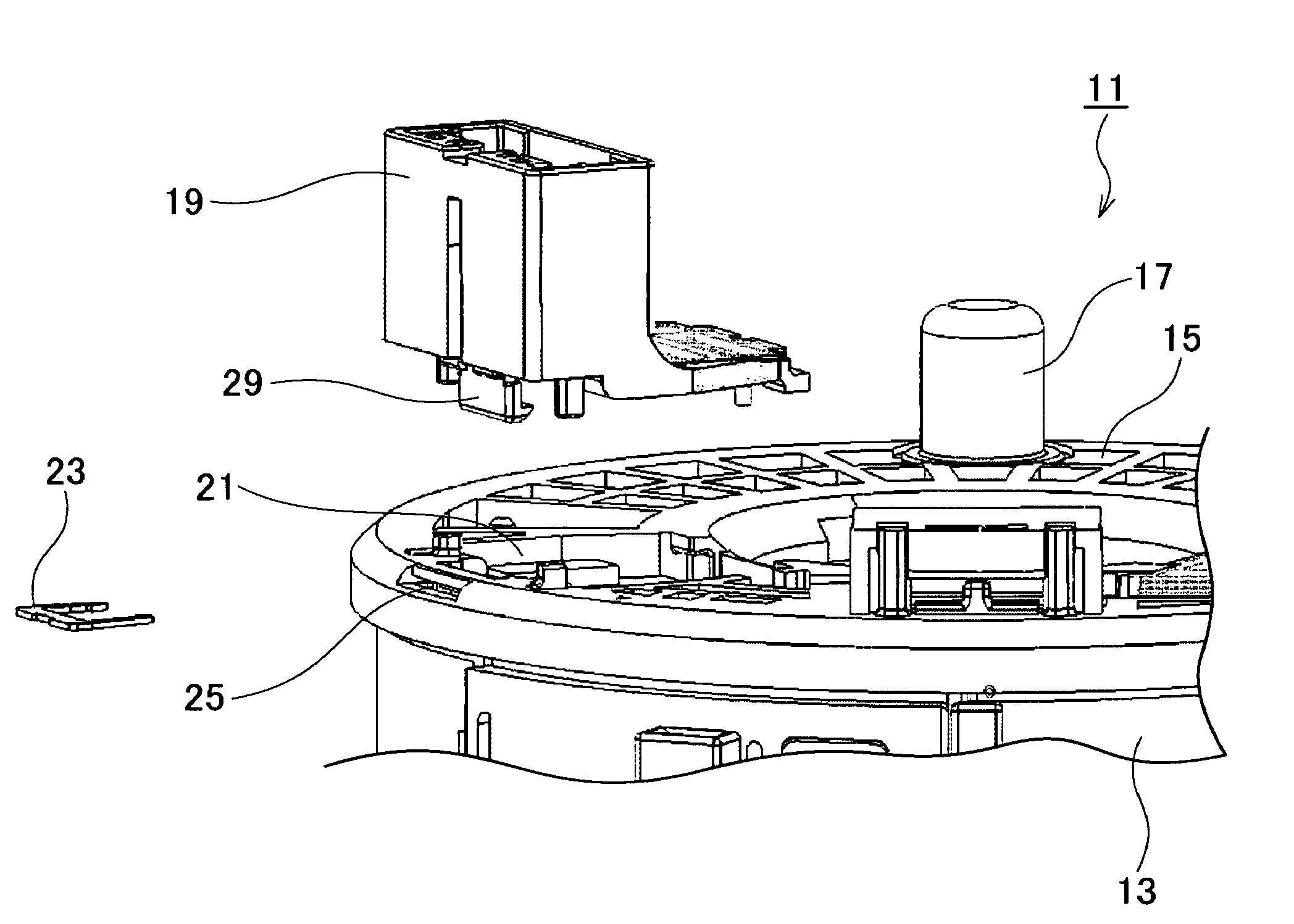
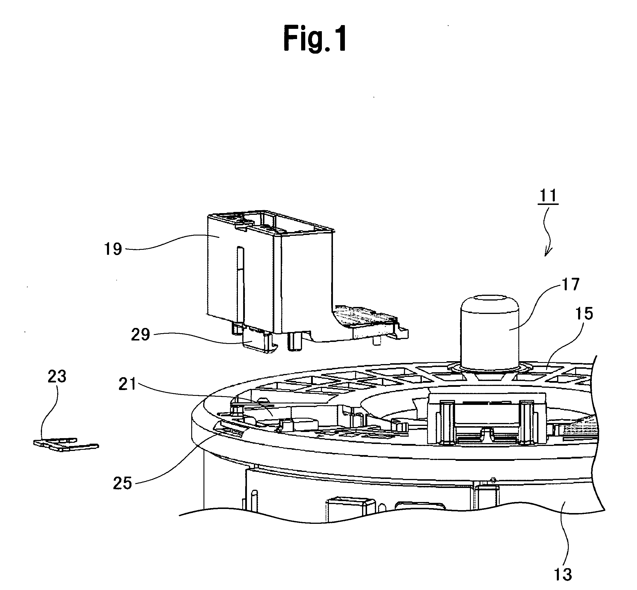
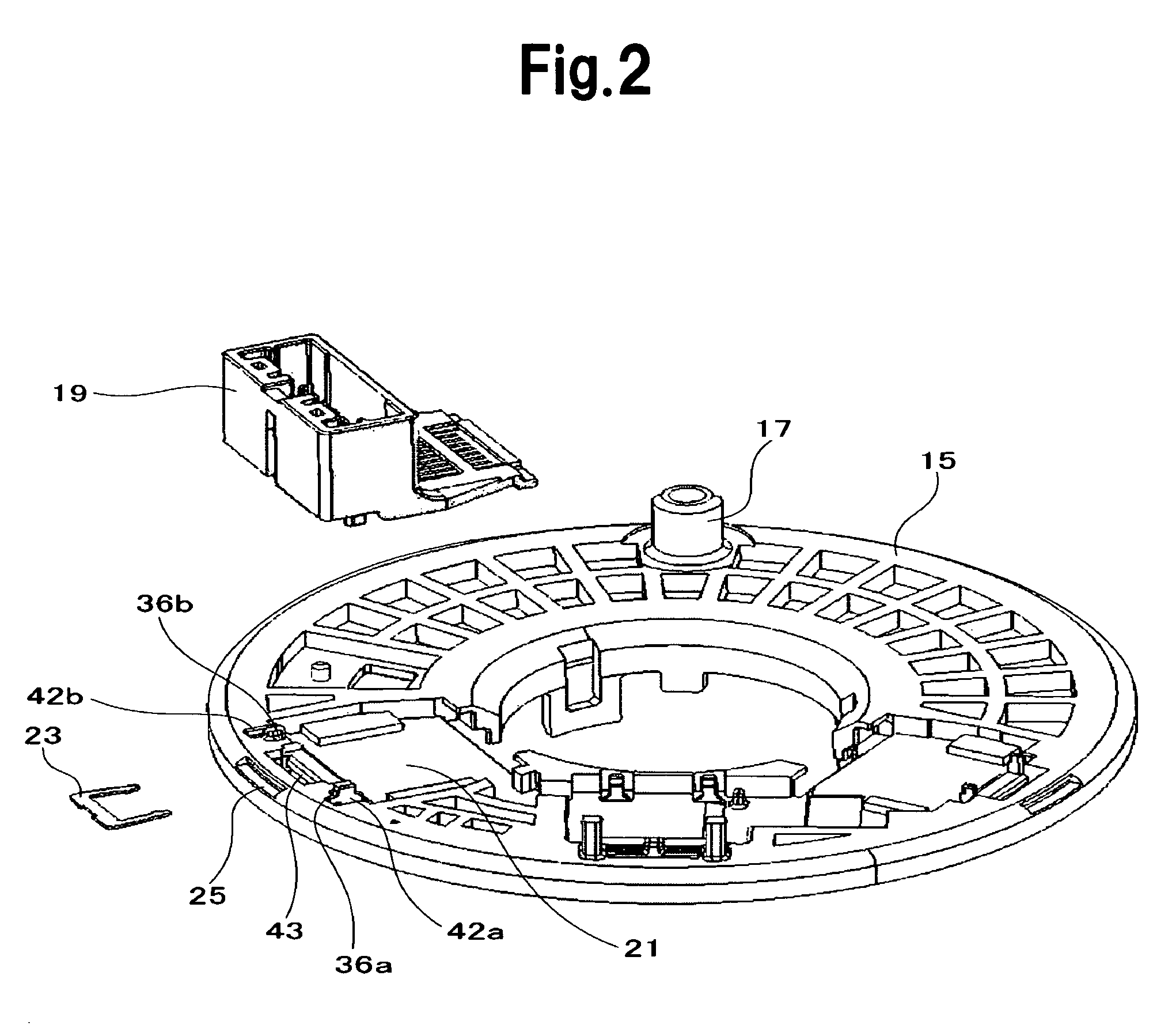
[0026]A detailed description will be given hereinafter with respect to a rotor housing of a rotary connector device for making electrical connection between a body side power supply of an automobile and an electric system of a steering wheel provided as an example of the first member, and with a connector housing fitted to the rotor housing provided as an example of the second member engagingly locked to the first member.

[0027]FIGS. 1 and 2 are broken perspective views of the rotor housing and its periphery, showing an overview of the locking structure according to an example of the present invention; FIG. 3 is a perspective view of the connector housing serving as a constituent element of an example of the present invention; FIG. 4 is a perspective view of the clip serving as a constituent element of an example of the present invention; FIG. 5 is a perspective view of a state in which the clip is fitted to the connector housing; FIG. 6 is a sectional perspective view o...


PUM


Abstract

A strength of engagingly locking a second member to a first member is remarkably improved without causing deterioration in workability, even when improvement in the locking strength between two members is attempted using a clip. In order to lock and fix a connector housing 19 to a rotor housing 15 in an erected state, an engagement force occurs and acts between a locking claw 27 and a locking part 45, via an insertion locking male part 29 provided in a connector housing 19. By this engagement force, the movement of the insertion locking male part 29 in the inserting/extracting direction is regulated. Further, by inserting the clip 23 from the direction almost at a right angle to the inserting direction of the insertion locking male part 29, a mechanical mutual action occurs between the clip 23 and a pair of insertion engagement parts 40a and 40b, thus secondarily regulating the movement of the insertion locking male part 29 in the inserting/extracting direction.

Description

BACKGROUND[0001]1. Technical Field[0002]The present invention relates to a structure for interlocking two members for locking and fixing a second member to a first member in an erected state. In particular, the present invention relates to a structure for interlocking two members, which is capable of remarkably improving strength of engagingly locking the second member to the first member.[0003]2. Background Art[0004]Conventionally, in order to further improve the strength of engagingly locking the second member to the first member, a technique of using a metal clip is known (Patent document 1).[0005]A connector housing with a latching mechanism of patent document 1 is composed of a pair of mutually engaging connector housings engaged, with one of the connector housings having a rotatable latching member, having a pair of elastic latching arms with tips bent inward, a center column, and an operating part; and the other connector housing having a cavity surrounded by front, rear, and...

Claims


Application Information

Patent Timeline
IPC IPC(8): F16B2/20
CPCH01R9/16H01R13/6272Y10T24/44026H01R13/741H01R13/6395
Inventor SATO, YASUHIROWAKANA, YOSHINORI
Owner NILES PARTS CO LTD
Why Eureka
Try Eureka