Variable valve actuating apparatus for internal combustion engine

Inactive Publication Date: 2009-01-08
HITACHI LTD
View PDF4 Cites 30 Cited by
  • Summary
  • Abstract
  • Description
  • Claims
  • Application Information

AI Technical Summary

Benefits of technology

[0006]It is desirable to provide a variable valve actuating apparatus or system for an internal combustion engine which is capable of freely controlling t

Problems solved by technology

This may cause the intake valves to interfere with the piston or the exhaust valves.
This however reduces the allowable range of each of the valve o

Method used


Image

  • Variable valve actuating apparatus for internal combustion engine
  • Variable valve actuating apparatus for internal combustion engine
  • Variable valve actuating apparatus for internal combustion engine

Examples


first embodiment

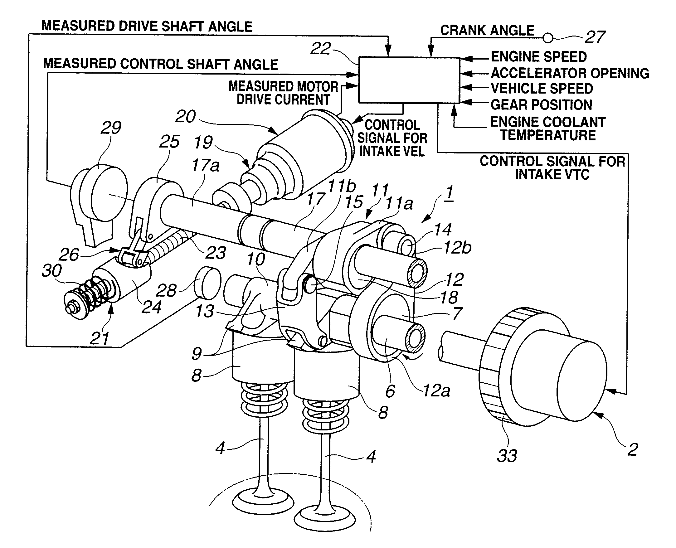
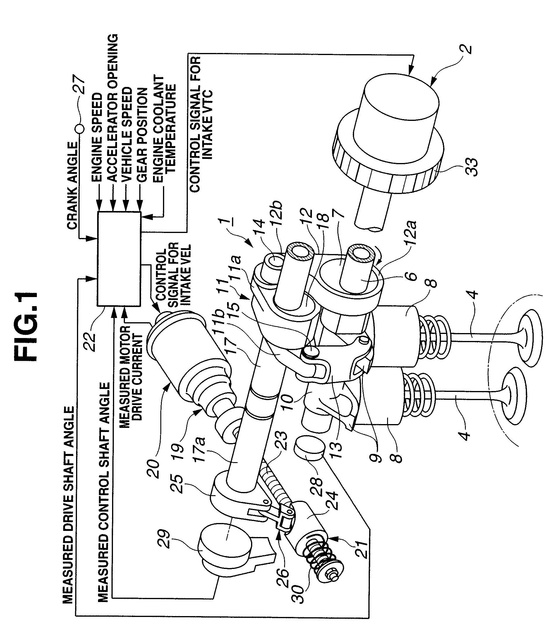
[0025]FIG. 1 schematically shows an internal combustion engine system including a variable valve actuating system or apparatus according to the present invention. In this embodiment, the internal combustion engine system includes a four-cycle gasoline internal combustion engine. As shown in FIG. 1, the variable valve actuating system includes an intake valve operating angle varying mechanism (intake valve lift varying mechanism, intake valve event and lift varying mechanism, or intake VEL) 1 as a first valve actuating mechanism for continuously varying (increasing or reducing) the lift and operating angle (operating period, or period when a valve is open) of intake valves 4, and an intake valve timing varying mechanism (intake valve phase varying mechanism, intake valve timing control mechanism, or intake VTC) 2 as a second valve actuating mechanism for continuously varying (advancing or retarding) a phase (maximum lift phase) of intake valves 4 so as to vary (advance or retard) the...

second embodiment

[0102]The following describes how the variable valve actuating system operates. In this embodiment, the variable valve actuating system is configured to set the exhaust valve maximum lift phase at a predetermined retarded position by the third valve actuating mechanism, when the accelerator opening is below the predetermined reference value; and set the exhaust valve maximum lift phase at a predetermined advanced position by the third valve actuating mechanism, when the accelerator opening is above the predetermined reference value, as described in detail below.

[0103]When the engine is at rest before started up after stopped, then the vane member 61 of the exhaust VTC 3 is mechanically and stably positioned and held at the position shown in FIG. 13 by the elastic force of coil springs 68, 69 and the lock mechanism. Accordingly, the exhaust VTC 3 is positioned so that the exhaust valve opening timing EVO and exhaust valve closing timing EVC are most advanced and held mechanically an...


PUM


Abstract

A variable valve actuating apparatus for an internal combustion engine includes an intake valve operating angle varying mechanism, and an intake valve timing varying mechanism. The intake valve timing varying mechanism includes a housing rotating in synchronization with a crankshaft, and a vane member coupled to a drive shaft for intake valve operation, and movably mounted in the housing. The vane member includes a vane defining first and second fluid pressure chambers on first and second opposite sides of the vane. A hydraulic circuit is arranged to rotate the vane member relative to the housing by supply and return of a brake fluid to and from the first and second fluid pressure chambers so as to change the intake valve maximum lift phase. Coil springs are arranged to bias the vane member relative to the housing in a direction to retard the intake valve maximum lift phase.

Description

BACKGROUND OF THE INVENTION[0001]The present invention relates to variable valve actuating apparatuses or systems for controlling opening and closing timings of intake valves and exhaust valves of internal combustion engines.[0002]U.S. Pat. No. 6,550,437 corresponding to Japanese Patent Application Publication No. 2002-256832 discloses a valve operating angle varying mechanism for an internal combustion engine arranged to vary an intake valve operating angle of the engine by an electronic system.[0003]U.S. Pat. No. 7,246,581 corresponding to Japanese Patent Application Publication No. 2006-070726 discloses a valve phase varying mechanism for an internal combustion engine arranged to vary an intake valve phase of the engine by a hydraulic system.SUMMARY OF THE INVENTION[0004]If the opening timing of intake valves is excessively advanced beyond top dead center, the lift height of the intake valves at top dead center is high. This may cause the intake valves to interfere with the pisto...

Claims


Application Information

Patent Timeline
IPC IPC(8): F01L9/02
CPCF01L1/3442F01L13/0015F01L13/0026F01L13/0063F01L2001/34426Y02T10/18F01L2013/0073F02D13/0211F02D13/0219F02D13/0261F01L2001/34483Y02T10/12
Inventor NAKAMURA, MAKOTOICHINOSAWA, YOSHINORITSUKADA, TOMOYAHARA, SEINOSUKEMURAKAMI, TOMOYUKI
Owner HITACHI LTD
Why Eureka
Try Eureka