Sheet Feeding Device and Image Forming Apparatus

a feeding device and image forming technology, applied in the direction of transportation and packaging, thin material processing, article separation, etc., can solve the problems of further continued operation and worsened sheet feeding performance, and achieve the effect of improving sheet feeding performan

Active Publication Date: 2009-01-08
BROTHER KOGYO KK
View PDF12 Cites 24 Cited by
  • Summary
  • Abstract
  • Description
  • Claims
  • Application Information

AI Technical Summary

Benefits of technology

[0095]Hereinabove, in the comparative example, the second time-lag is caused as well as the first time-lag until the rising of the pressing plate 11 is actually stopped after the sheet feeding roller 9 reaches the first release position X1. On the contrary, in the present embodiment, before the sheet feeding roller 9 reaches the first release position X1, the engagement of the second engaging lever 62 with the second engaged portion 72 has already been released, and the cam gear 63 has been driven and rotated. Accordingly, in the present embodiment, the second time-lag is not caused at the time when the pressing plate 11 reaches the first release position X1. Furthermore, in the present embodiment, the engagement of the second engaging lever 62 with the second engaged portion 72 is released earlier than in the comparative example. Hence, a rising height amount of the pressing plate 11 is more constrained in the present embodiment than in the comparative example. Thus sheet feeding performance can be improved.

Problems solved by technology

Therefore, it is unfortunate that the lifting operation might be further continued even after the loading portion reaches the predetermined height and a sheet feeding performance might be worsened.

Method used


Image

  • Sheet Feeding Device and Image Forming Apparatus
  • Sheet Feeding Device and Image Forming Apparatus
  • Sheet Feeding Device and Image Forming Apparatus

Examples


Embodiment Construction

[0040]It is noted that various connections are set forth between elements in the following description. It is noted that these connections in general and, unless specified otherwise, may be direct or indirect and that this specification is not intended to be limiting in this respect.

[0041]Hereinafter, an embodiment according to aspects of the present invention will be described with reference to the accompany drawings. It is noted that, in each drawing, an outline arrow denotes a direction in which a sheet feeding roller 9 or each gear is moved or rotated.

Overall Configuration in Embodiment

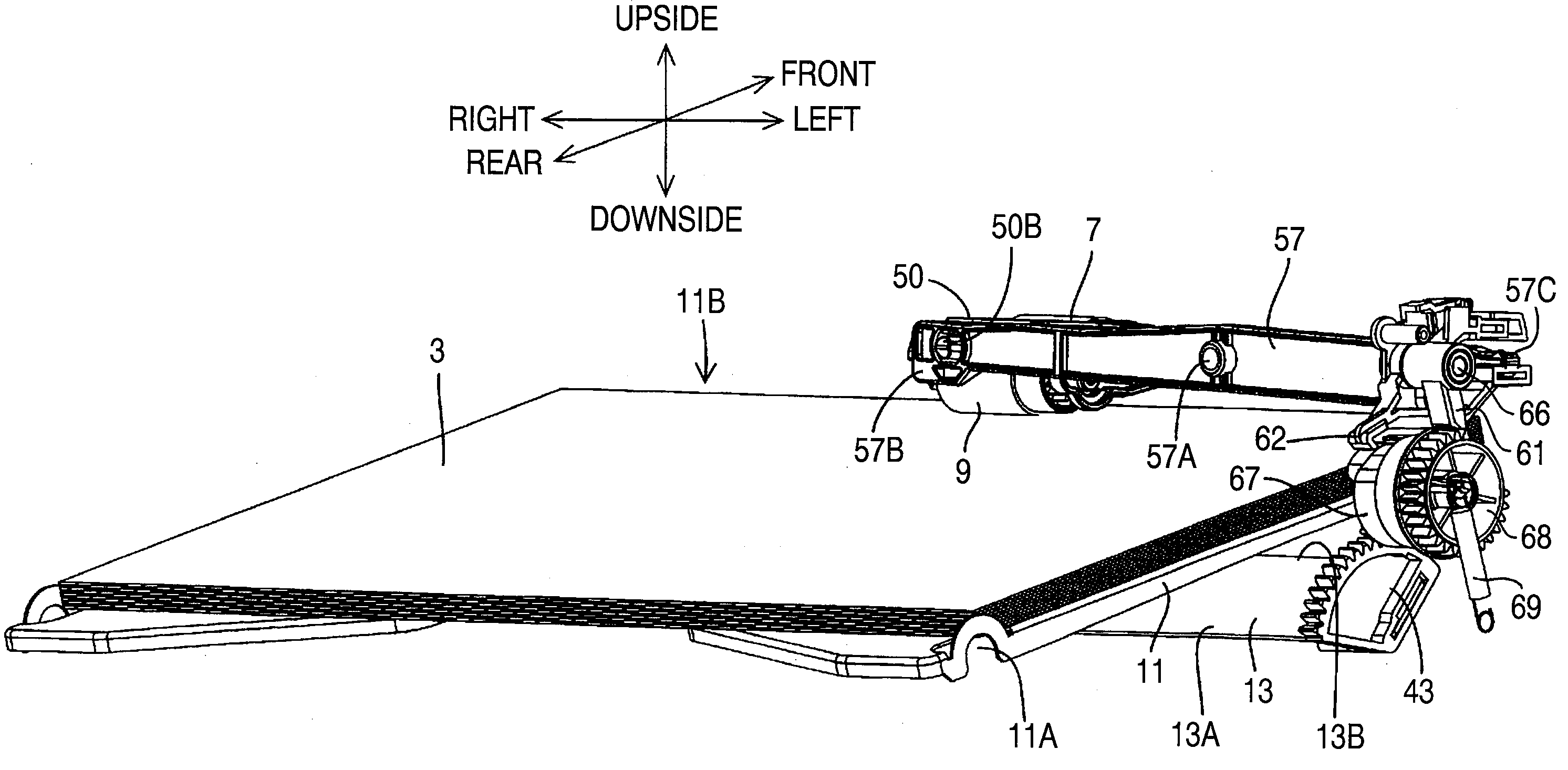
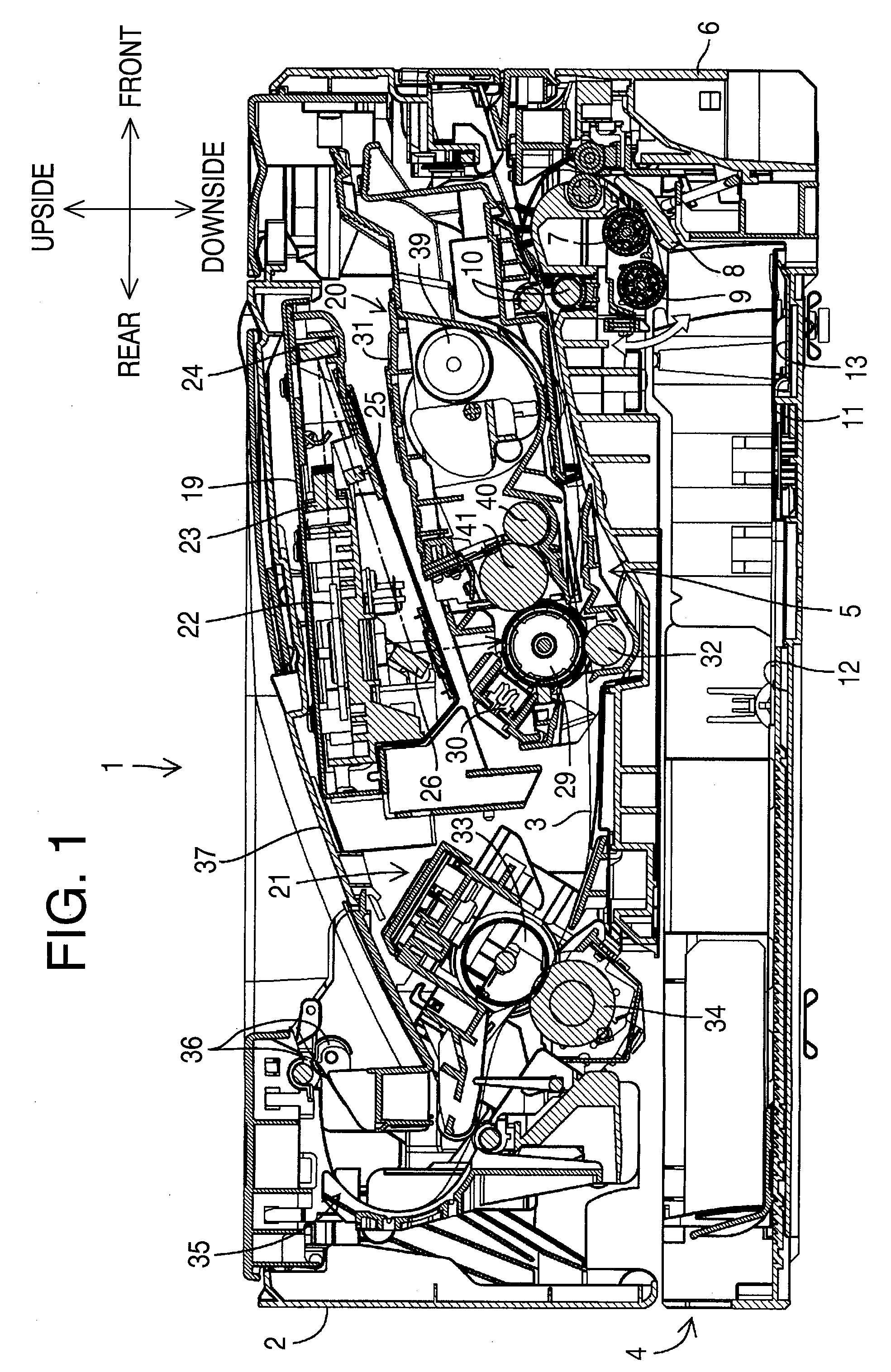
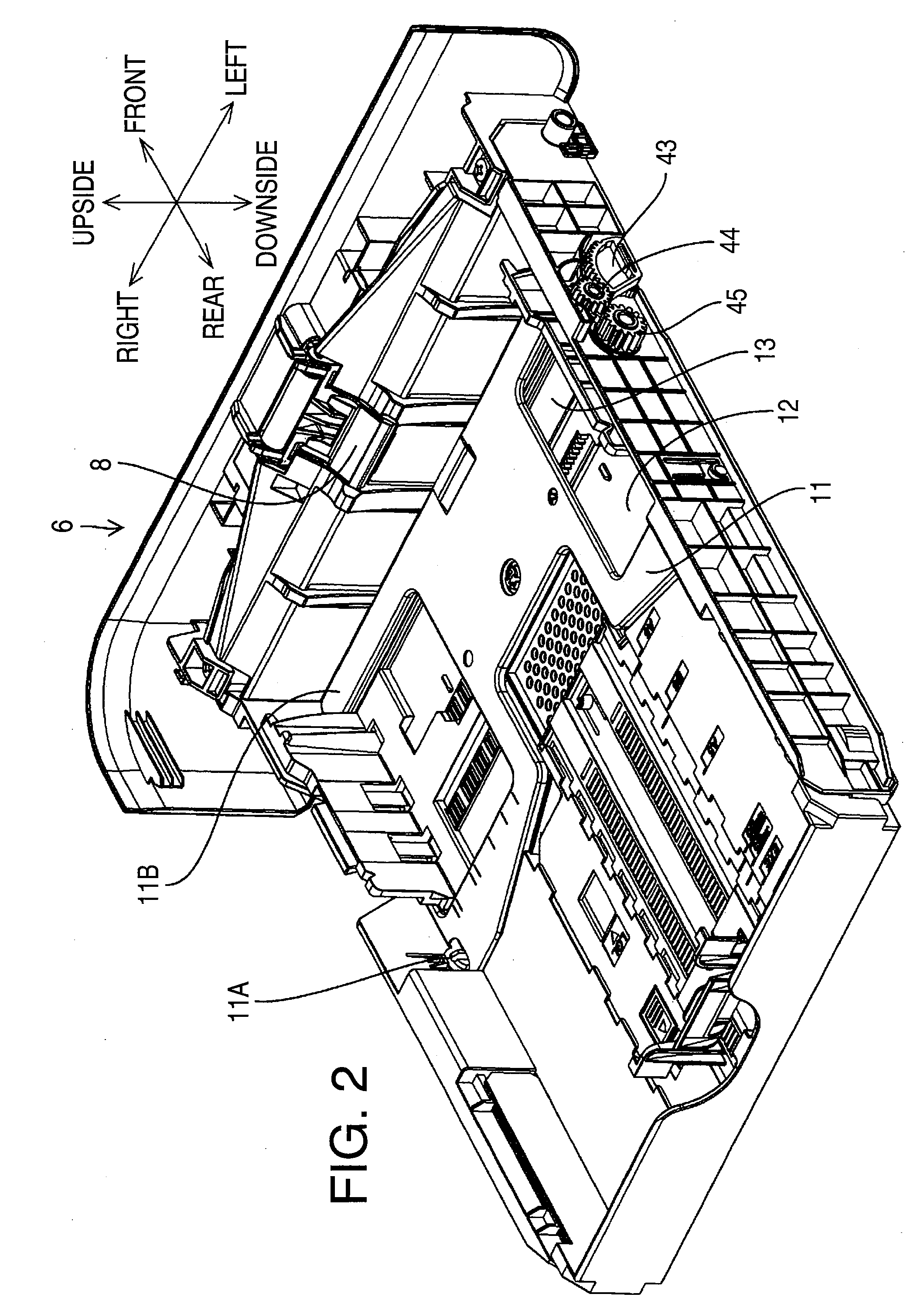
[0042]FIG. 1 is a cross-sectional side view showing a configuration of a laser printer 1 (hereinafter, simply referred to as a printer 1). FIG. 2 is a perspective view of a storage cassette 6. FIGS. 3 to 5 are perspective views showing respective states in process of lifting a pressing plate 11.

[0043]The printer 1 is provided with a main body casing 2, a feeder unit 4 configured to feed a sheet 3,...


PUM


Abstract

A sheet feeding device includes a loading portion configured to be loaded with a sheet, a lifting mechanism that lifts the loading portion in an operating state and stops the loading portion in an stopped state, a cam configured to be rotated alternately to a first rotational position for setting the lifting mechanism to the operating state and to a second rotational position for setting the lifting mechanism to the stopped state, a detecting unit having a contact portion movable up and down while contacting the sheet on the loading portion, which detects whether the sheet reaches a first height based upon the movement of the contact portion thereof, and a control unit configured to rotate the cam before the detecting unit detects that the sheet reaches the first height and to stop the cam in the second rotational position in response to the detection by the detecting unit.

Description

CROSS-REFERENCE TO RELATED APPLICATION[0001]This application claims priority under 35 U.S.C. §119 from Japanese Patent Application No. 2007-176317 filed on Jul. 4, 2007. The entire subject matter of the application is incorporated herein by reference.BACKGROUND[0002]1. Technical Field[0003]The following description relates to one or more sheet feeding techniques for an image forming apparatus.[0004]2. Related Art[0005]Among image forming apparatuses, for example, there is an apparatus provided with a loading portion configured to be loaded with a sheet, a lifting mechanism configured to lift the loading portion, and a detecting unit configured to detect whether the loading portion reaches a predetermined height. It is noted that the predetermined height represents such a height that a sheet on the loading portion can be fed to a carrying route inside a main body of the apparatus.[0006]In the meantime, a configuration has been known, in which ON / OFF control of a lifting operation by ...

Claims


Application Information

Patent Timeline
Patent Type & Authority Applications(United States)
IPC IPC(8): B65H1/04
CPCB65H3/0607B65H3/0684B65H2403/53B65H2403/512B65H2403/47B65H2701/1912
Inventor KURODA, NAOMI
Owner BROTHER KOGYO KK
Why Eureka
Try Eureka