Normalizing capacitive sensor array signals

a capacitive sensor and array technology, applied in the field of capacitive sensor arrays, can solve the problems of large signal loss, conventional user interface design signal loss, inaccurate position determination across the face of the user interface panel, etc., and achieve the effect of facilitating accurate position information, overcoming signal loss, and high impedance capacitive substrates

Inactive Publication Date: 2009-01-08
MONTEREY RES LLC
View PDF73 Cites 65 Cited by
  • Summary
  • Abstract
  • Description
  • Claims
  • Application Information

AI Technical Summary

Benefits of technology

[0006]Accordingly, embodiments of the present invention are directed to a system and method for processing position signal information using high impedance capacitive sensors. The processing of the signal information overcomes the signal loss

Problems solved by technology

The greater the distance from the connection of the sensor array, the greater signal loss that occurs due to series impedance as the signal travels through the array to the detector logic.
The non-uniform signal loss characteristic may lead to inaccurate pos

Method used


Image

  • Normalizing capacitive sensor array signals
  • Normalizing capacitive sensor array signals
  • Normalizing capacitive sensor array signals

Examples


example circuits

[0025]FIGS. 2 and 4-6 illustrate example components used by various embodiments of the present invention. Although specific components are disclosed in circuits 200, 400, 500, and 600 it should be appreciated that such components are examples. That is, embodiments of the present invention are well suited to having various other components or variations of the components recited in systems 200, 400, 500, and 600. It is appreciated that the components in systems 200, 400, 500, and 600 may operate with other components than those presented, and that not all of the components of systems 200, 400, 500, and 600 may be required to achieve the goals of systems 200, 400, 500, and 600.

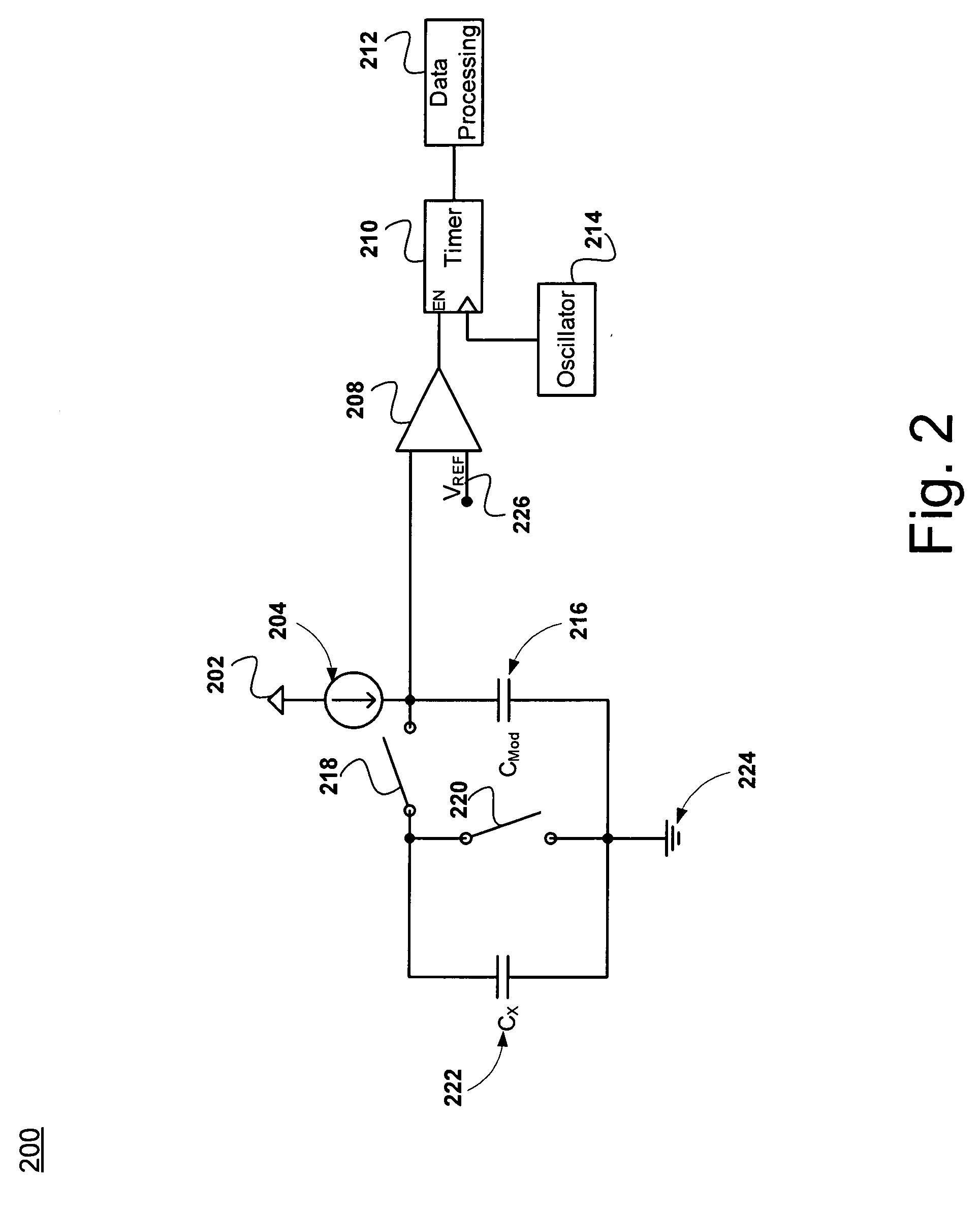
[0026]FIG. 2 shows an exemplary sensor circuit 200, in accordance with one embodiment of the present invention. Sensor circuit 200 includes Vdd signal 202, current source 204, comparator 208, timer 210, data processing module 212, oscillator 214, reference voltage 226, external modification capacitor 216, ground...

example operations

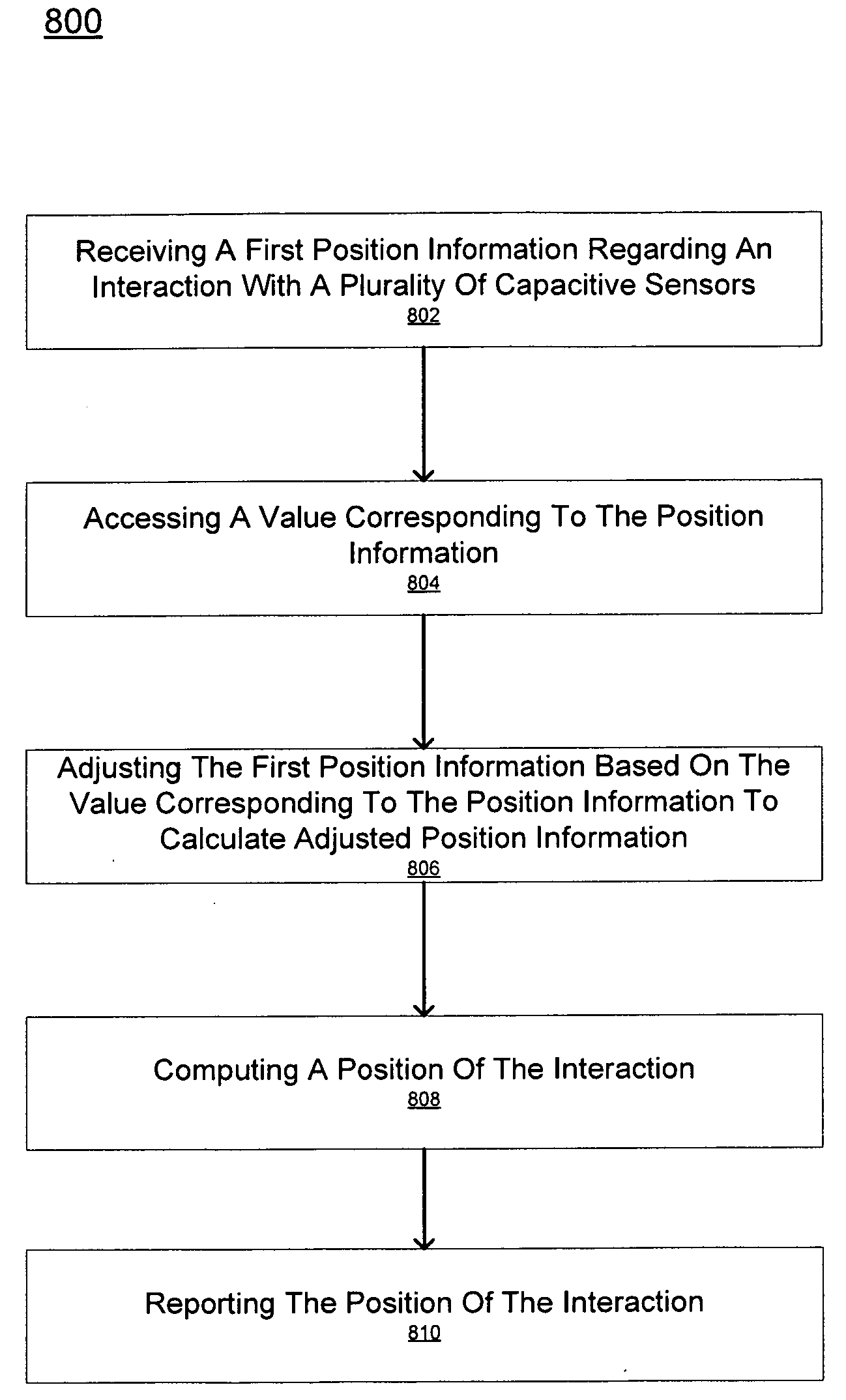
[0067]With reference to FIGS. 8-10, exemplary flowcharts 800-1000 each illustrate example blocks used by various embodiments of the present invention. Although specific blocks are disclosed in flowcharts 800-1000, such blocks are examples. That is, embodiments are well suited to performing various other blocks or variations of the blocks recited in flowcharts 800-1000. It is appreciated that the blocks in flowcharts 800-1000 may be performed in an order different than presented, and that not all of the blocks in flowcharts 800-1000 may be performed.

[0068]FIG. 8 shows a flowchart 800 of an exemplary process for reporting position information, in accordance with an embodiment of the present invention. The blocks of flowchart 800 may be performed by a data processing portion (e.g., data processing module 212 or data processing module 514) of a sensor circuit (e.g., sensor circuits 200 and 400-600).

[0069]At block 802, first position information regarding an interaction is received from ...


PUM


Abstract

An embodiment of the present invention is directed to a method for processing a position signal. The method includes receiving a first position signal from a capacitive sensor and determining a proximity of the capacitive sensor to a connection of an array of capacitive sensors. The sensitivity of the capacitive sensor is then adjusted and a second position signal is received from the capacitive sensor. The second position signal may then be reported. The present invention facilitates more accurate readings from an array of capacitive sensors.

Description

RELATED U.S. APPLICATIONS[0001]This application claims the benefit of and priority to copending provisional patent application, Ser. No. 60 / 947,903, Attorney Docket Number CYPR-CD2007183R, entitled “Method For Normalizing Signal From A High-Impedance Array of Capacitive Sensors,” with filing date Jul. 3, 2007, and hereby incorporated by reference in its entirety.FIELD OF INVENTION[0002]Embodiments of the present invention generally relate to capacitive sensor arrays.BACKGROUND OF THE INVENTION[0003]As computing technology has developed, user interface devices have advanced correspondingly. User interfaces have become increasingly significant in the usability of a computing device.[0004]One particular user interface becoming increasingly popular is touch screen or track pad which uses an array of capacitive sensors using high impedance capacitance substrates. The sensor array is typically connected to detection logic via a portion of the sides of the array. The sensor array is divide...

Claims


Application Information

Patent Timeline
IPC IPC(8): G01R27/26
CPCG01D5/24
Inventor SEGUINE, RYAN D.
Owner MONTEREY RES LLC
Why Eureka
Try Eureka