Dispersion-managed soliton transmission system with guiding filters

a transmission system and filter technology, applied in electromagnetic transmission, electrical equipment, transmission, etc., can solve the problems of dispersion of light pulses, difficult to distinguish and detect the data represented by light pulses, and inability to broaden the pulse in tim

Inactive Publication Date: 2007-12-25
LUCENT TECH INC
View PDF4 Cites 0 Cited by
  • Summary
  • Abstract
  • Description
  • Claims
  • Application Information

AI Technical Summary

Benefits of technology

[0033]The present invention also includes an embodiment where signal loss in transmission lines having very large amplifier periods, e.g., 80 km or 120 km, is overcome through the use of intermediate Raman amplification.

Problems solved by technology

One type of distortion affecting light pulses is dispersion.
This interaction is another type of distortion, in which the pulses tend to be moved from their proper positions in time and so cause error.
If pulse widths become still larger, pulses in successive bit periods will overlap, making it difficult to distinguish and detect the data represented by those pulses.
However, the differential phase shift caused by SPM does not broaden the pulse in time.
However, optical amplifiers along the transmission line create spontaneous emission noise which causes small, random alterations in the central frequencies of the pulses.
If the cumulative dispersion encountered by pulses is large, the corresponding large differences in arrival times can result in the pulses being received at the incorrect time slot or bit period.
This leads to errors in decoding the information represented by the pulses.
Other types of distortion are encountered in optical systems employing wavelength division multiplexing or “WDM”.
In general, these effects have the potential to bring about a significant exchange of energy and momentum between the pulses which creates timing jitter and amplitude jitter, the latter referring to fluctuations in the intensity of the pulses.
This results in a low spectral efficiency for a transmission line having this prior art D map.
Furthermore, at or near D=0, the path average pulse energy of solitons in this transmission line depends critically on both D and the pulse width τ. This critical dependence makes this transmission line less practical for use since in real world systems D and generated pulse widths can vary.
Also, a prior art transmission line having a D map similar to FIG. 3 is deficient because the D map period is not the same as the amplifier period.
Creating transmission lines where the D map period is multiple amplifier periods long is often disadvantageous.
For one thing, the long period tends to produce too great pulse breathing, with the result of excessive adjacent pulse interaction.
However, if these prior art D maps are altered so that the amplifier period is made to be the same as the D map period, the pulse breathing in the +D section of the D map period becomes highly asymmetric.
This in turn also results in excessive pulse interaction.
This uneven compensation results in asymmetric pulse breathing.

Method used


Image

  • Dispersion-managed soliton transmission system with guiding filters
  • Dispersion-managed soliton transmission system with guiding filters
  • Dispersion-managed soliton transmission system with guiding filters

Examples


first embodiment

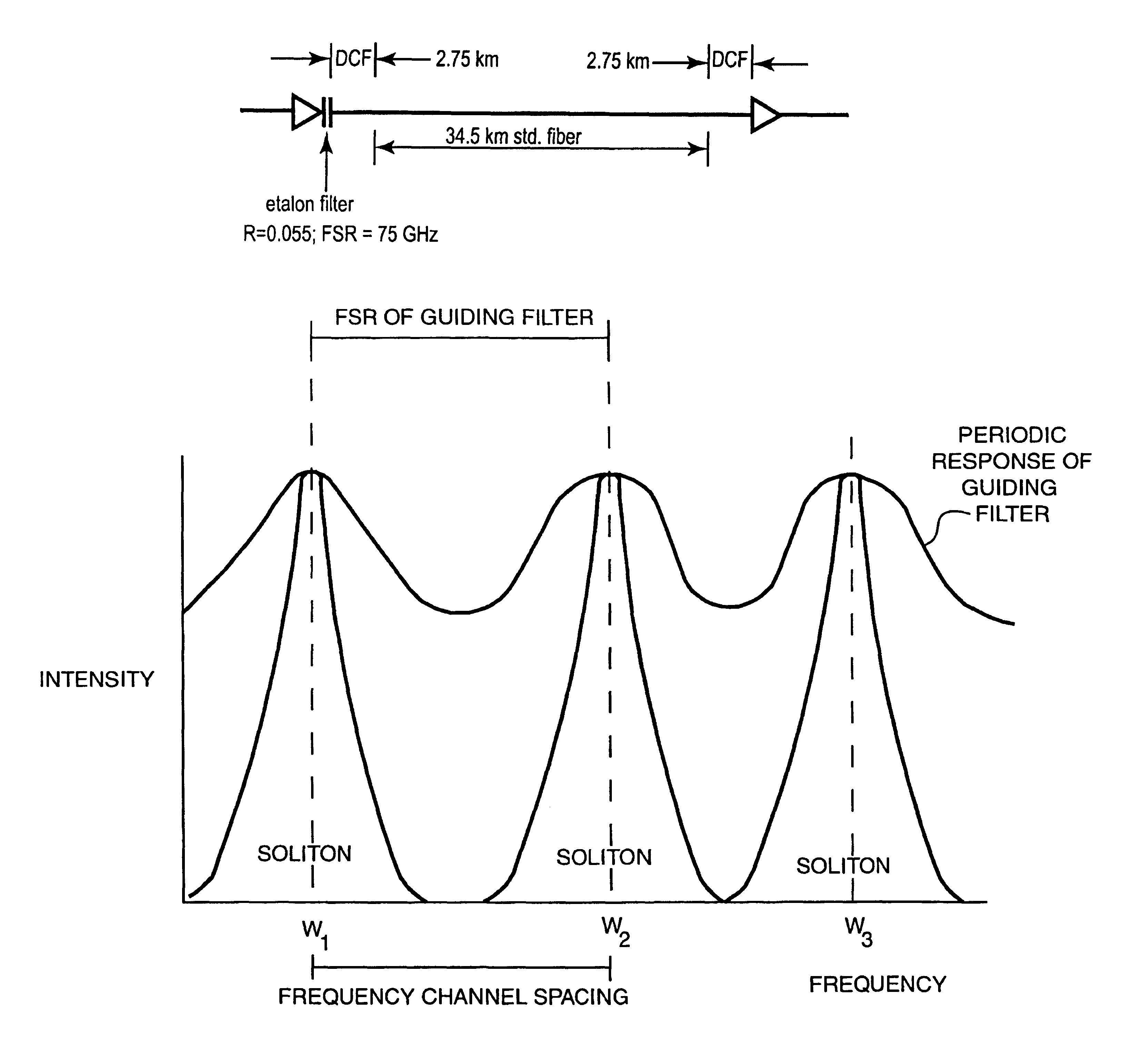
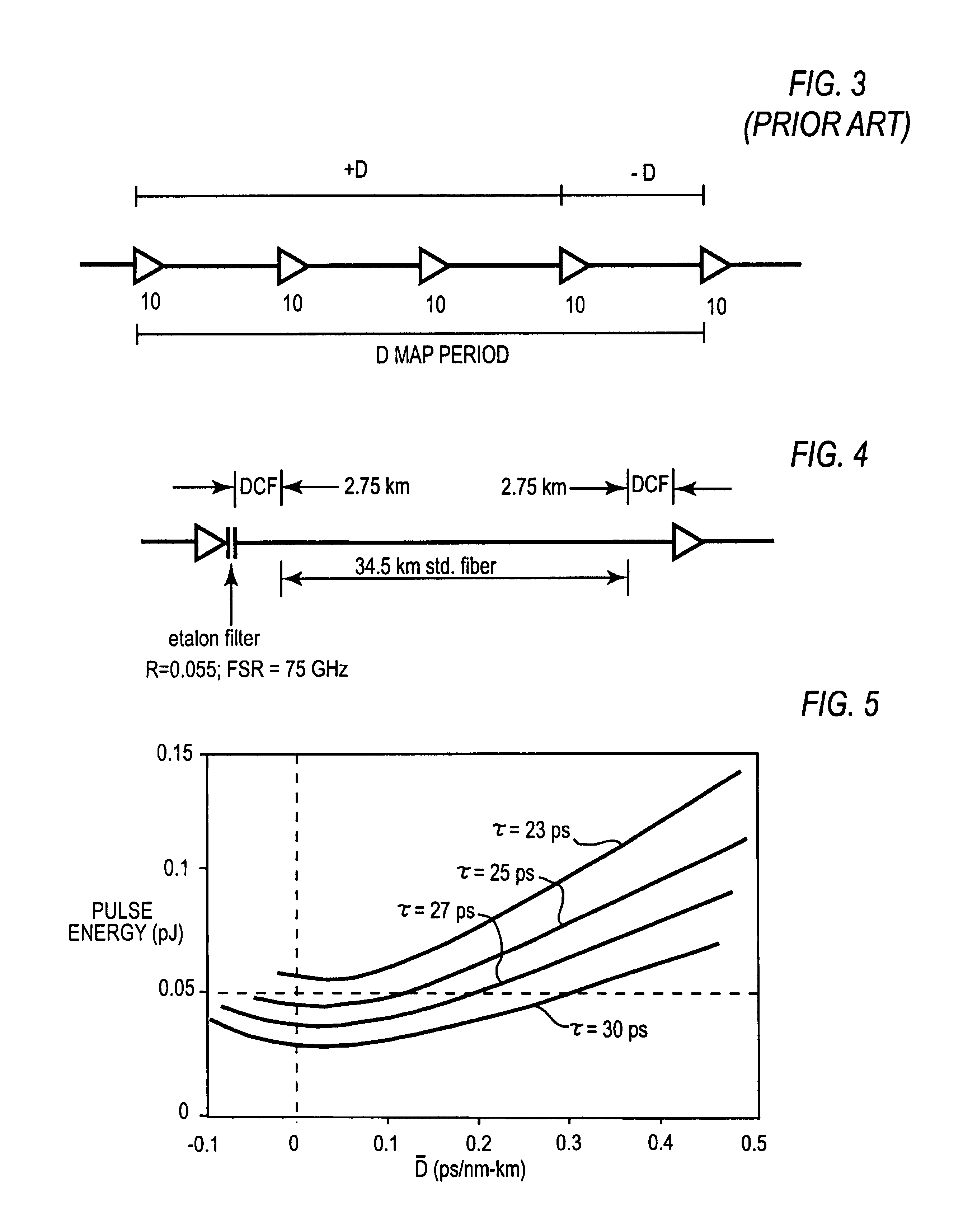
[0045]FIG. 4 shows the present invention. The figure shows a D map period of a dispersion managed transmission line for use in propagating solitons. In the specific example shown, the D map period contains three segments of fiber—two segments of dispersion compensating fiber, or “DCF”, of 2.75 km length sandwiching one 34.5 km segment of standard fiber. The specific properties of each type of fiber is listed in Table 1. The number of fiber segments, the types of fiber used, and the lengths of these segments are not a limitation on the invention, however, and need not be the same as those shown in the figure. The only limitation in this regard is that the number of fiber segments, the type of fiber, and the lengths of the segments must be chosen in accordance with the principles of dispersion management. In other words, the number of fiber segments, the type of fiber, and the lengths of the segments must be chosen such that |Dloc| at any point along the D map is high, i.e., not less ...

third embodiment

[0064]As stated previously, the problem with such long amplifier spacings is that if standard power levels are used at the amplifiers the optical signal is too weak at the end of the period, and if power is increased so that the signal remains strong at the end of the period, the amplifiers become complex and expensive and the increased power constantly threatens to cause optical damage and greatly increases error producing non-linear effects. the invention solves this problem by providing a secondary amplification of the signal within the D map period through Raman amplification.

[0065]In Raman amplification, light of a higher frequency than the frequency of the signal pulses is injected into the optical fiber carrying the signal pulses. The higher frequency light here is known as the pump light. As the signal pulses pass through the area of fiber excited by the pump light, they extract energy from the pump light through what is known as the Raman effect. Thus, the signal pulses are...


PUM


Abstract

A new dispersion managed soliton transmission system where the D map period is the same as the amplifier period and the pulse breathing the in the +D sections of the D maps is approximately symmetrical. Pulse breathing symmetry by one or both of two techniques. In one technique a guiding filter is placed at the beginning of the D map period such that the guiding filter reduces the bandwidth of soliton pulses passing through it by a minimum amount. Consequently, pulse breathing symmetry is restored. The path average pulse energy vs. D behavior of solitons propagating through the D map is changed such that (1) solitons of modest bandwidths have adequate energy at or near D=to provide for error-free transmission over transoceanic distances at or near D=0, and (2) such that the path average pulse energy is nearly independent of D, at or near D=0 for solitons of various pulse widths. The transmission system having this D map is much more tolerant of variations in D and pulse width than the prior art. Another technique uses two different types of +D fiber in the +D section so that there is a step change in the ratio of D divided by the cross-sectional area of the fiber, or “Aeff”, as solitons propagate from one type of +D fiber to the other type of +D fiber in the +D section. This step change in DAeff
nullifies the effects of the variation in pulse intensity thereby restoring the pulse breathing symmetry. Furthermore, through the use of intermediate Raman amplification, signal loss in transmission lines having very large amplifier periods, e.g., 80 km or 120 km, is overcome.

Description

[0001]This application claims the benefit of U.S. Provisional Application No. 60 / 101,765, filed Sep. 25, 1998, and U.S. Provisional Application No. 60 / 101,773, also filed Sep. 25, 1998.FIELD OF THE INVENTION[0002]The present invention relates generally to the field of fiber optic communications and specifically to systems for transmitting dispersion-managed solitons using guiding filters.BACKGROUND OF THE INVENTION[0003]Data transmission using optical fibers involves the propagation of pulses of light through the fibers. A light pulse generated at a specific frequency ω actually consists of a spectrum, i.e., a distribution of energy over a band of frequencies, with the peak of the spectrum occurring at frequency ω. The frequency at which the peak of a pulse occurs is known as the central frequency of the pulse. FIG. 1 shows a light pulse generated at frequency ω with a peak intensity I. The bandwidth of the pulse is defined as the range of frequencies wherein the frequency component...

Claims


Application Information

Patent Timeline
Patent Type & Authority Patents(United States)
IPC IPC(8): H04B10/00H04B10/12
CPCH04B10/25077
Inventor GORDON, JAMES POWERMAMYSHEV, PAVEL VIKTOROVICHMOLLENAUER, LINN FREDERICK
Owner LUCENT TECH INC
Why Eureka
Try Eureka