LED flat-plate type multi-chip high power light source

a multi-chip, led light source technology, applied in the field of illumination devices, can solve the problems of inability to withstand heat, large thermal resistance, and limited heat conductivity of the structure, and achieve the effects of good heat dissipation capability, bad heat dissipation capability, and high power

Inactive Publication Date: 2009-01-08
SHENZHEN HOYOL OPTO ELECTRONICS
View PDF6 Cites 8 Cited by
  • Summary
  • Abstract
  • Description
  • Claims
  • Application Information

AI Technical Summary

Benefits of technology

[0008]The present invention provides a LED flat-plate type multi-chip high power light source with good heat dissipating capability, with the heat dissipating substrate being capable of completely combining with the user radiator, to solve the technical problem that the conventional LED lamps have bad heat dissipating capability and can not afford the high power LED to dissipate heat.

Problems solved by technology

As a semiconductor device, LED has the inherent disadvantage of not enduring heat.
The structure comprises disadvantages that sectional area of the heat conducting pole 02 is small, the heat conducting path is long, and the thermal resistance is great.
For the thermal resistance is great, the structure can only conduct limited heat.
So with the structure, only 1-3 W light source can be produced, and the light source of above 5 W will have short useful life due to absence of conducting heat.
If the power supply wire is led out from the inverse of the heat dissipating substrate, it can only be settled in the following two ways; 1, using a metal block thicker than the length of the lead wire as a transition between the heat dissipating substrate and the radiator, which will bring the thermal resistance and thermal accumulate to increase; 2, drilling and making insulation on the shell of the lamps, which will introduce problems of both appearance and waterproofness.
So, setting the lead wire at the inverse of the heat dissipating substrate neither is convenient to fix, nor can make the combined area of the heat dissipating substrate and the user radiator up to 100%, which will weaken the heat dissipating effect.

Method used


Image

  • LED flat-plate type multi-chip high power light source
  • LED flat-plate type multi-chip high power light source
  • LED flat-plate type multi-chip high power light source

Examples


Embodiment Construction

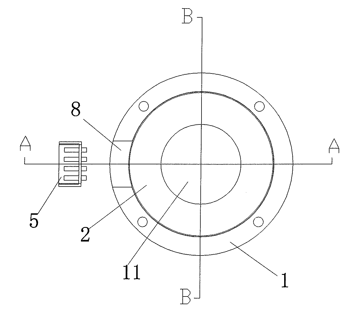
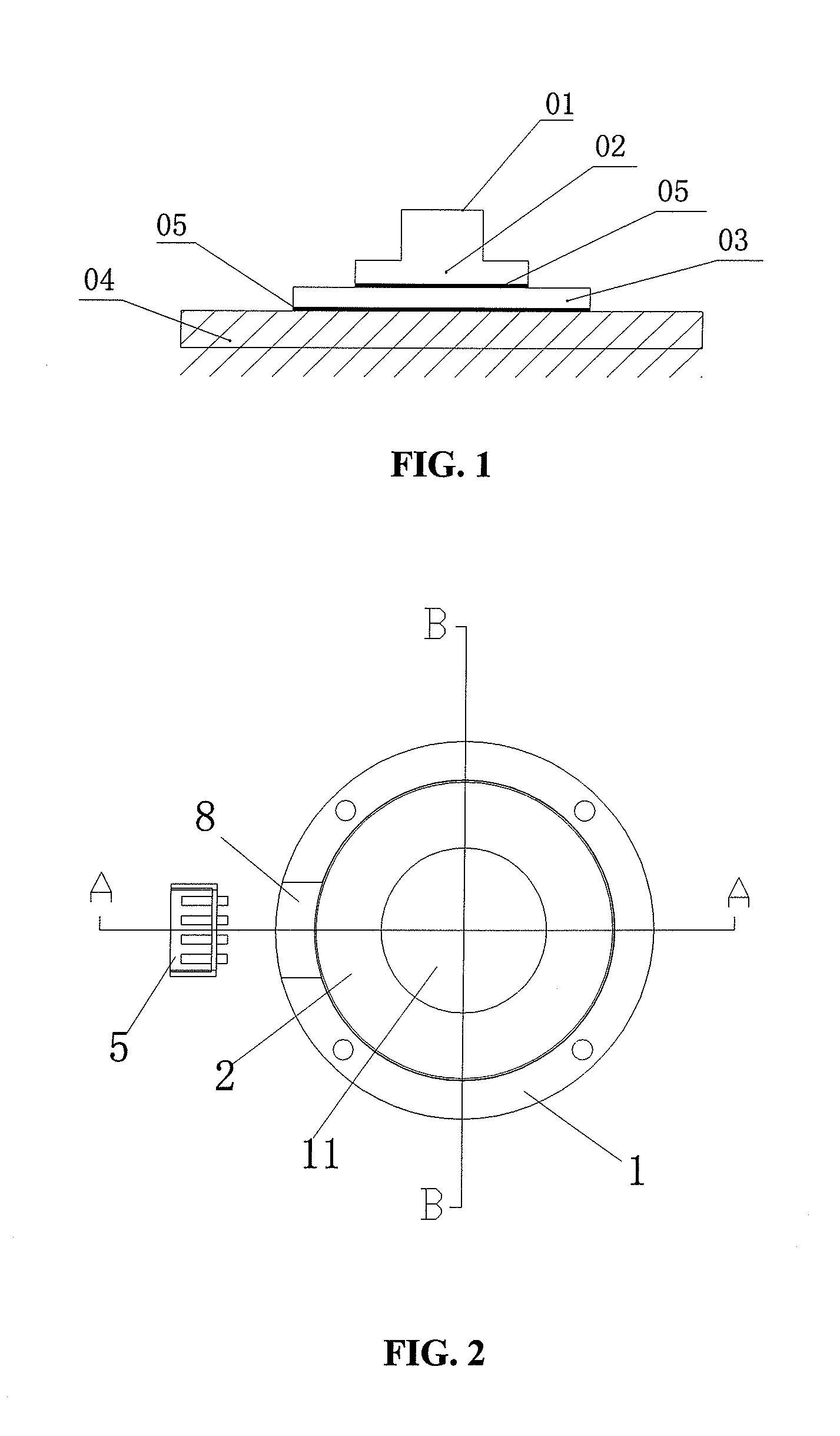
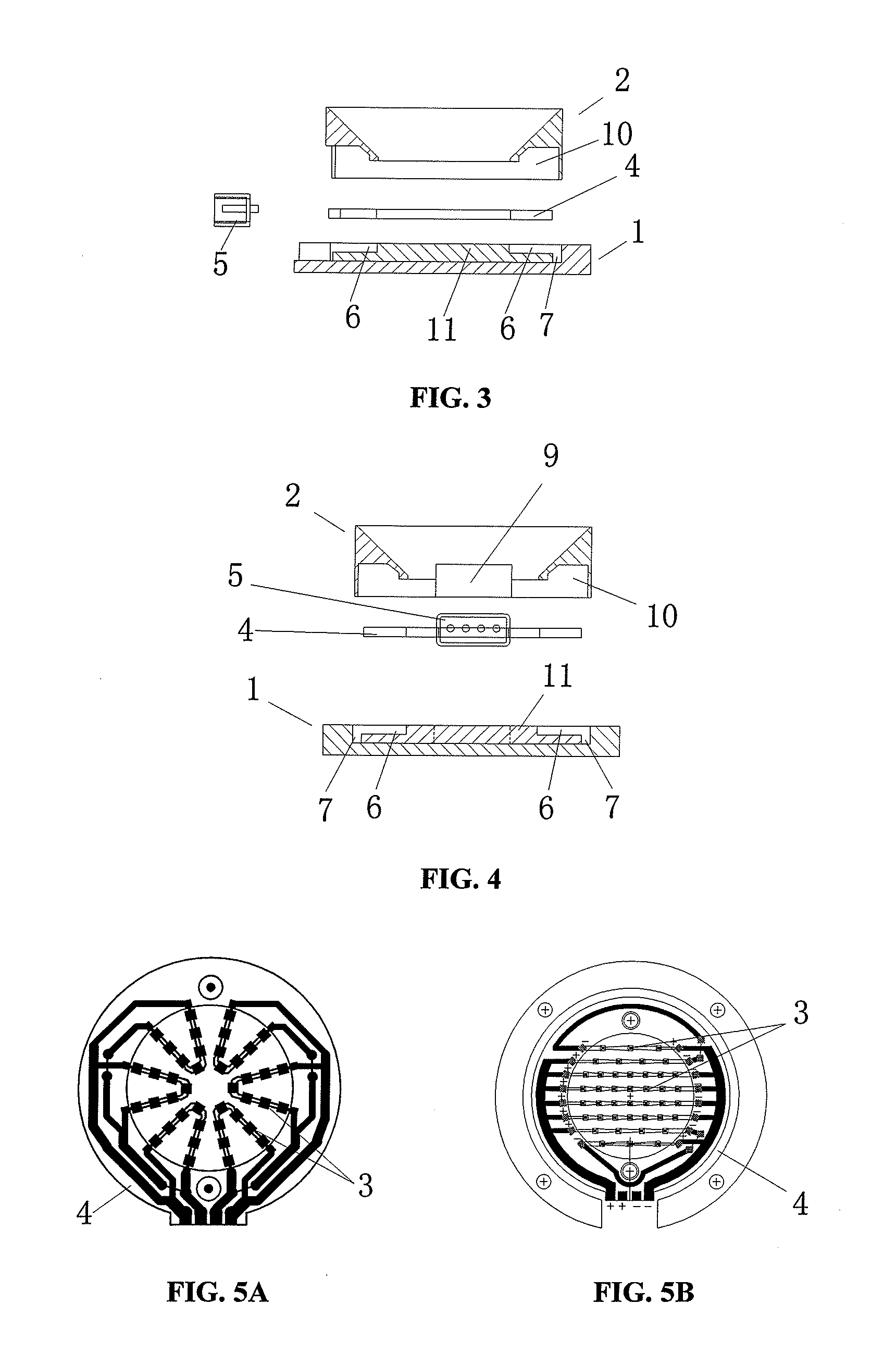
[0021]FIG. 2 and FIG. 3 illustrate the basic structure of a preferred embodiment of the present invention. The LED flat-plate type multi-chip high power light source comprises a heat dissipating substrate 1, a reflecting cover 2 mounted on the heat dissipating substrate 1, LEDs 3 mounted on the heat dissipating substrate 1 and in the reflecting cover 2, a circuit board 4 embedded in the heat dissipating substrate 1 connecting to the LEDs 3, and the circuit board 4 also connecting to a socket 5 set in the heat dissipating substrate 1. The heat dissipating substrate 1 is made of high heat conduction metal, to ensure the heat dissipating substrate 1 to have the capability of good heat conduction and dissipating.

[0022]As shown in FIG. 4, the heat dissipating substrate 1 has a round shape, and the circuit board 4 embedded in the heat dissipating substrate 1 has a circle shape. On the heat dissipating substrate 1, a circle shape groove 6 matching the shape of the circuit board 4 is provid...


PUM


Abstract

The present invention provides a LED flat-plate type multi-chip high power light source comprising a heat dissipating substrate, a reflecting cover mounted on the heat dissipating substrate, LEDs mounted on the heat dissipating substrate and in the reflecting cover, a circuit board embedded in the heat dissipating substrate connecting to the LEDs, and the circuit board also connecting to a socket set in the heat dissipating substrate. The heat dissipating substrate is made of high heat conduction metal. In the present invention, the heat dissipating substrate is made of high heat conduction metal, and the heat conducting pole is abolished. Comparing with the conventional art, the present invention decreases the heat dissipating path, increases the sectional area, and eliminates the intermediate link of high thermal resistance.

Description

RELATED APPLICATIONS[0001]The present application is based on, and claims priority from, China Application Number 200710075903.6, filed Jul. 6, 2007, the disclosure of which is hereby incorporated by reference herein in its entirety.BACKGROUND OF THE INVENTION[0002]1. Field of the Invention[0003]The present invention relates to an illuminating device, particularly relates to a high power LED light source.[0004]2. Description of the Related Art[0005]As a new type of light source, LED gradually concerns all the countries in the world. Comparing with the traditional light source, LED involves the advantages: 1, having better safety, belonging to cold light source device, being driven in low voltage, having firm structure, not falling to pieces; having long useful life, lasting 50-100 thousand hours in a good heat dissipation condition, which is much longer than other light sources; 2, having rich colors, being regulated and controlled easily; 3, improving luminous efficiency greatly ye...

Claims


Application Information

Patent Timeline
Patent Type & Authority Applications(United States)
IPC IPC(8): F21V29/00
CPCF21K9/00F21V29/505F21V29/20F21Y2105/003F21Y2105/12F21Y2105/10F21V29/70
Inventor YANG, XIANGHONGCHANG, BAOYANXU, ZHENG
Owner SHENZHEN HOYOL OPTO ELECTRONICS
Why Eureka
Try Eureka