
Adjustable mount for securing a camera, video camera, etc. to another member

Inactive Publication Date: 2009-01-08
DEWITT DOUGLAS D
View PDF15 Cites 27 Cited by
  • Summary
  • Abstract
  • Description
  • Claims
  • Application Information

AI Technical Summary

Benefits of technology

[0010]A further object of this invention is to provide an adjustable mount for supporting a piece of equipment, such as a camera, which is relatively easy and inexpensive to manufacture.
[0011]Still another object of this invention is to provide an adjustable mount for supporting a piece of equipment, such as a camera, which is easy to adjust and manipulate in the outdoors.
[0012]Still further, an object of this invention is to provide an adjustable mount for supporting a piece of equipment, such as a camera, which will not rust or corrode.

Problems solved by technology

One problem that currently exists with mounting such cameras is that most of the cameras are designed to be strapped to the trunk of a tree.
However, if the tree to which the camera is to be secured is not in the right location relative to the trail or path, the camera may not be at the most advantageous angle to take pictures of animals walking down the trail or path.
However, some of these mounts are limited as to their adjustability and many are relatively expensive.
Some can only hold the camera in a single fixed position, other mounts have a single plane of rotation, and still other mounts can rotate but do not have the ability to pivot up and down or sideways.
Another drawback is that some mounts are designed such that only one style or brand of camera can be attached to them.
This means that a person having a different style or brand of camera cannot use such a mount.

Method used


Image

  • Adjustable mount for securing a camera, video camera, etc. to another member
  • Adjustable mount for securing a camera, video camera, etc. to another member
  • Adjustable mount for securing a camera, video camera, etc. to another member

Examples


Embodiment Construction

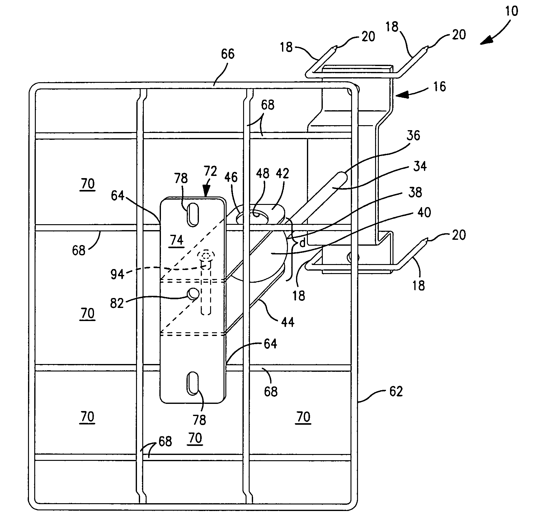
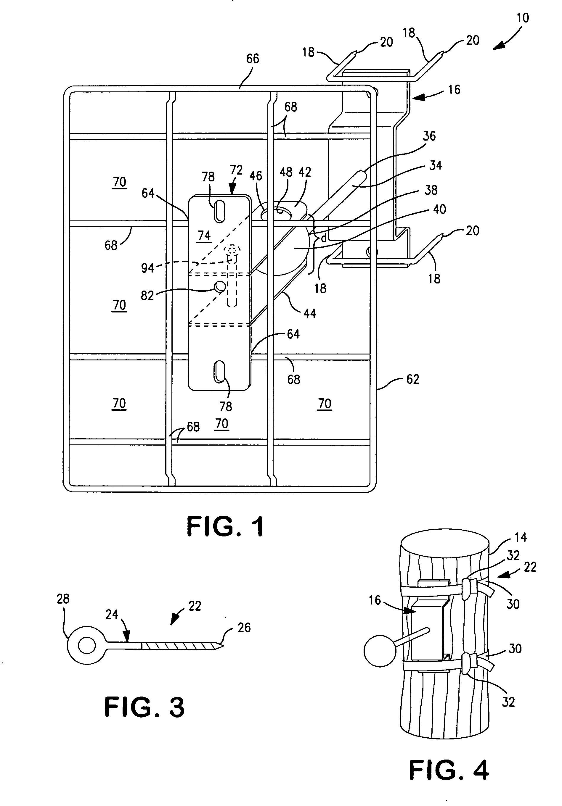
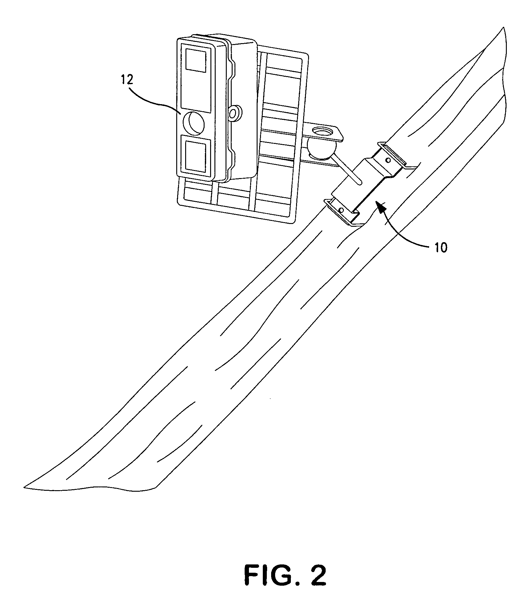
[0029]Referring to FIGS. 1 and 2, an adjustable mount 10 is shown for securing a piece of equipment 12 in a desired position relative to another member or object 14. The piece of equipment 12 can be a camera, a camera with or without a flash unit, a 35 millimeter camera, an outdoor camera, an outdoor game camera, a portable camera, an INSTAMATIC® camera, a video camera, a film camera, a digital camera, a spotting scope, an optical device, a surveillance mechanism, a piece of photographic equipment, a surveying instrument, an engineering instrument, a motion detector, a sound recorder, a video projector, a video recorder, etc. Almost any type of equipment or device 12 can be secured to the adjustable mount 10.

[0030]The adjustable mount 10 can be removably secured or attached to another member or object 14. The other member or object 14 can be a stationary member, a movable member, an upstanding member, a member aligned at an angle to the ground, a member aligned adjacent to the groun...


PUM


Abstract

An adjustable mount is disclosed for securing a piece of equipment 12 to another member. The adjustable mount includes a first member attachable to the other member and an elongated member secured at one end to the first member. A sphere is attached to the opposite end of the elongated member. A pair of plates is aligned parallel to one another and is spaced apart by a set distance. Each of the pair of plates has an aperture formed therein which is sized to mate with a portion of the sphere to enable the pair of plates to rotate, pivot and / or swivel on the sphere. The adjustable mount further includes a support structure secured to the pair of plates which is capable of having a piece of equipment 12 attached thereto. Lastly, the adjustable mount includes an adjustment mechanism capable of changing the set distance between the pair of plates.

Description

CROSS REFERENCE TO RELATED APPLICATION[0001]This patent application is a regular patent application claiming priority to U.S. Provisional Patent Application Ser. No. 60 / 958,085, filed Jul. 2, 2007.FIELD OF THE INVENTION[0002]This invention relates to an adjustable mount for securing a piece of equipment, such as a camera, a video camera, etc., to another member, such as a tree or post. More specifically, this invention relates to an adjustable mount for securing a camera to a tree, deadfall, stump, etc. outdoors so that photos can be taken of wildlife, such as deer, bear, turkeys, etc.BACKGROUND OF THE INVENTION[0003]Today, many hunters and outdoor enthusiasts are using cameras, video cameras, digital cameras, etc. to photograph wildlife and / or to find out what trails or paths their potential game are using. For example, a whitetail deer hunter can attach a camera to a tree located adjacent to a trail or path and record if any deer are using the trail or path and at what time during...

Claims


Application Information

Patent Timeline
IPC IPC(8): G03B17/00A47F7/00
CPCF16M11/14G03B17/56F16M13/02G03B17/561
Inventor DEWITT, DOUGLAS D.
Owner DEWITT DOUGLAS D
Learn More