Connector with bifurcated contact arms

a contact arm and connector technology, applied in the direction of coupling contact member, coupling device connection, connection contact member material, etc., can solve the problems of increasing insertion force, relatively expensive manufacturing, and complicated design

Active Publication Date: 2009-01-08
MOLEX INC
View PDF51 Cites 52 Cited by
  • Summary
  • Abstract
  • Description
  • Claims
  • Application Information

AI Technical Summary

Benefits of technology

[0006]It is therefore a general object of the present invention to provide a backplane-daughterboard connector which is adapted for more reliable interfacing with a backplane connector for high speed electrical signal transmission.
[0008]A further object is to provide a connector of the foregoing type in which the bifurcated contacts have a streamlined design which permits uniform contacts spacing.
[0009]Still another object is to provide a connector of the above kind in which the bifurcated contacts are relatively simple in design and lend themselves to economical manufacture.
[0011]In other embodiments, the longer second arm can be “J” shaped and can hook back upon itself so that the distal end of the second arm is linearly aligned with the first arm. The second arm can have a width generally approximate the width of the first arm but less than the combined width of the first and second arms. When the daughter card connector is mated with the pin header, the longer second arm initially will come into sliding contact with a corresponding pin, then the straight, shorter second arm will come into sliding contact with the corresponding pin. Accordingly, the bifurcated contact provides two redundant points of contact with the pin. An advantage of providing two redundant points of contact is to accommodate misalignment or physical distortion among the bifurcated contacts and the pins.
[0012]In another aspect of the invention, there can be formed on the respective distal ends of the first and second arms of the bifurcated contact a corresponding first contact protuberance and a second contact protuberance. With respect to the second arm, the contact protuberance can be formed on the either the “L” or “J” shaped distal portion that is offset with respect to the main linear portion of the second arm. Because the “L” or “J” shaped distal portion of the second arm extends transversely with respect to the first arm, the contact protuberances can be aligned along an imaginary line delineated along the direction of extension of the first straight arm extending from the mating face. In a further aspect of the invention, the contact protuberances within a wafer can all be oriented in the same direction. An advantage of orienting the protuberances in one direction is to enable close packing of the bifurcated contacts extending from the mating edge.

Problems solved by technology

As can be appreciated though, the bifurcated arms of the leads can interfere with placement of adjacent contacts, can require offsetting or uneven contact positioning, and can increase insertion forces during mating of the connector with a pin header.
They also can be complicated in design and relatively costly to manufacture.

Method used


Image

  • Connector with bifurcated contact arms
  • Connector with bifurcated contact arms
  • Connector with bifurcated contact arms

Examples


Embodiment Construction

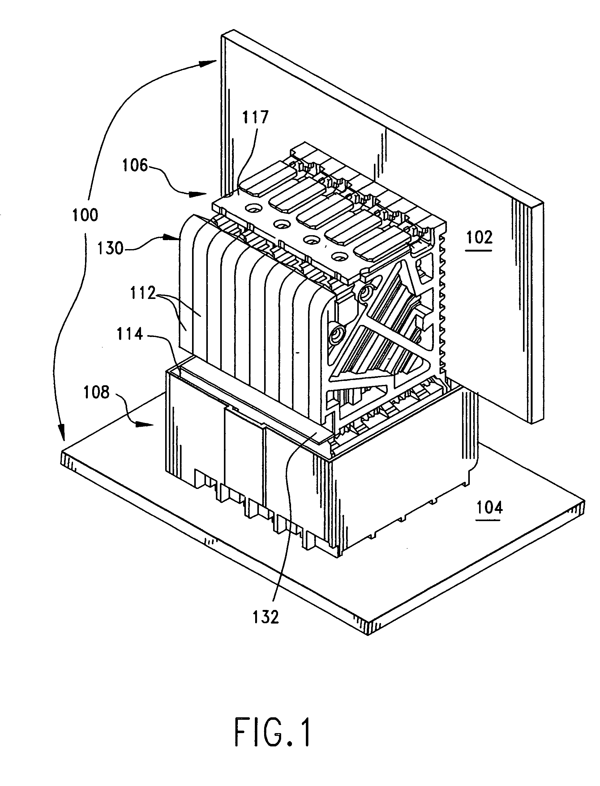
[0024]Referring now to FIG. 1, there is shown an illustrated backplane connector 100 used to electrically and / or physical connect together a backplane printed circuit board 104 (“PCB”) and a daughtercard PCB 102. The backplane connector can be of a two-piece construction and includes a backplane pin header 108 mounted to the backplane PCB and a daughtercard connector 106 mounted to the daughtercard 102. In order to facilitate assembly and disassembly of the backplane PCB and daughtercard PCB, the daughtercard connector and the pin header can be detachably pluggable or mateable together. In the illustrated embodiment, because the backplane PCB 104 and the daughtercard PCB 102 are arranged at a right angle to each other, the backplane connector 100 is a right angle connector and the electrical paths through connector 100 accordingly transition or change direction through a 90° bend. However, in other embodiments, the backplane PCB 104 and daughtercard PCB 102 can be arranged at other ...


PUM


Abstract

A backplane electrical connector electrically and physically connects a daughter card printed circuit board to a backplane printed circuit board. The electrical connect can be of a two-piece construction including a daughtercard connector mateable with a pin header. The daughtercard connector can be assembled from a plurality of wafers which each can include a plurality of conductive leads. The wafers can have an attachment edge that lies adjacent to the daughtercard and a mating edge that is directed toward the pin header. Each conductive lead can include a bifurcated contact extending from the mating edge and each can have a first arm and a second arm. The first and second arms can provide two redundant points of contact with a corresponding conductive pin disposed in the pin header.

Description

REFERENCE TO RELATED APPLICATIONS[0001]This application claims the domestic benefit of U.S. Provisional Application Ser. No. 60 / 936,387, filed on Jun. 20, 2007, which disclosure is hereby incorporated by reference.BACKGROUND OF THE INVENTION[0002]The present invention relates generally to back plane connectors, and more particularly, to a daughtercard connector having terminals adapted for improved, more reliable transmission of high speed differential signals.[0003]Routers, servers and similar electronic communication and processing devices typically include multiple printed circuit boards (PCBs) arranged and operatively connected together. For example, a backplane board can be provided to which one or more daughter cards are connected. In order to conserve space and promote air cooling over the backplane and daughtercards, the daughtercards can be arranged parallel to each other and at a right angle to the backplane. Electrically connecting the backplane and daughtercards together...

Claims


Application Information

Patent Timeline
Patent Type & Authority Applications(United States)
IPC IPC(8): H01R13/02H01R12/71
CPCH01R13/514H01R12/737H01R12/724H01R12/716H01R13/6587
Inventor LAURX, JOHNREGNIER, KENT
Owner MOLEX INC
Why Eureka
Try Eureka