Method and apparatus for obtaining electronic oscillotory pressure signals from an inflatable blood pressure cuff

a technology of electronic oscillotory pressure and blood pressure cuff, which is applied in the field of methods and apparatus for obtaining electronic oscillotory pressure signals from inflatable blood pressure cuffs, can solve the problems of high cost, difficult to discern exact timing and magnitude of waves, and performance still leaves much to be desired

Inactive Publication Date: 2009-01-08
PULSECOR LTD
View PDF11 Cites 16 Cited by
  • Summary
  • Abstract
  • Description
  • Claims
  • Application Information

AI Technical Summary

Benefits of technology

[0027]Thus, the present invention provides means for extracting useful parameters of central and peripheral cardiovascular system performance, without requiring a direct measurement of waveforms from the heart or aorta.

Problems solved by technology

These reflection waves are identifiable in arterial pressure tracings, but the exact timing and magnitude of the waves are difficult to discern.
Attempts have been made to automate this procedure, however, the cost of doing so is high, and performance still leaves much to be desired in practice.
However, these methods do not measure pressure changes directly, and so require significant, error-prone mathematical transformation to estimate the arterial pressure wave.
There are two main problems with using a cuff pulse waveform as a basis for deriving information about a person's health.
There is generally found instability and irreproducibility in the measurement of a cuff-pulse wave.

Method used


Image

  • Method and apparatus for obtaining electronic oscillotory pressure signals from an inflatable blood pressure cuff
  • Method and apparatus for obtaining electronic oscillotory pressure signals from an inflatable blood pressure cuff
  • Method and apparatus for obtaining electronic oscillotory pressure signals from an inflatable blood pressure cuff

Examples


Embodiment Construction

[0043]The preferred embodiments of the present invention will now be described with reference to FIGS. 1-10 of the drawings. Identical elements in the various figures are designated with the same reference numerals.

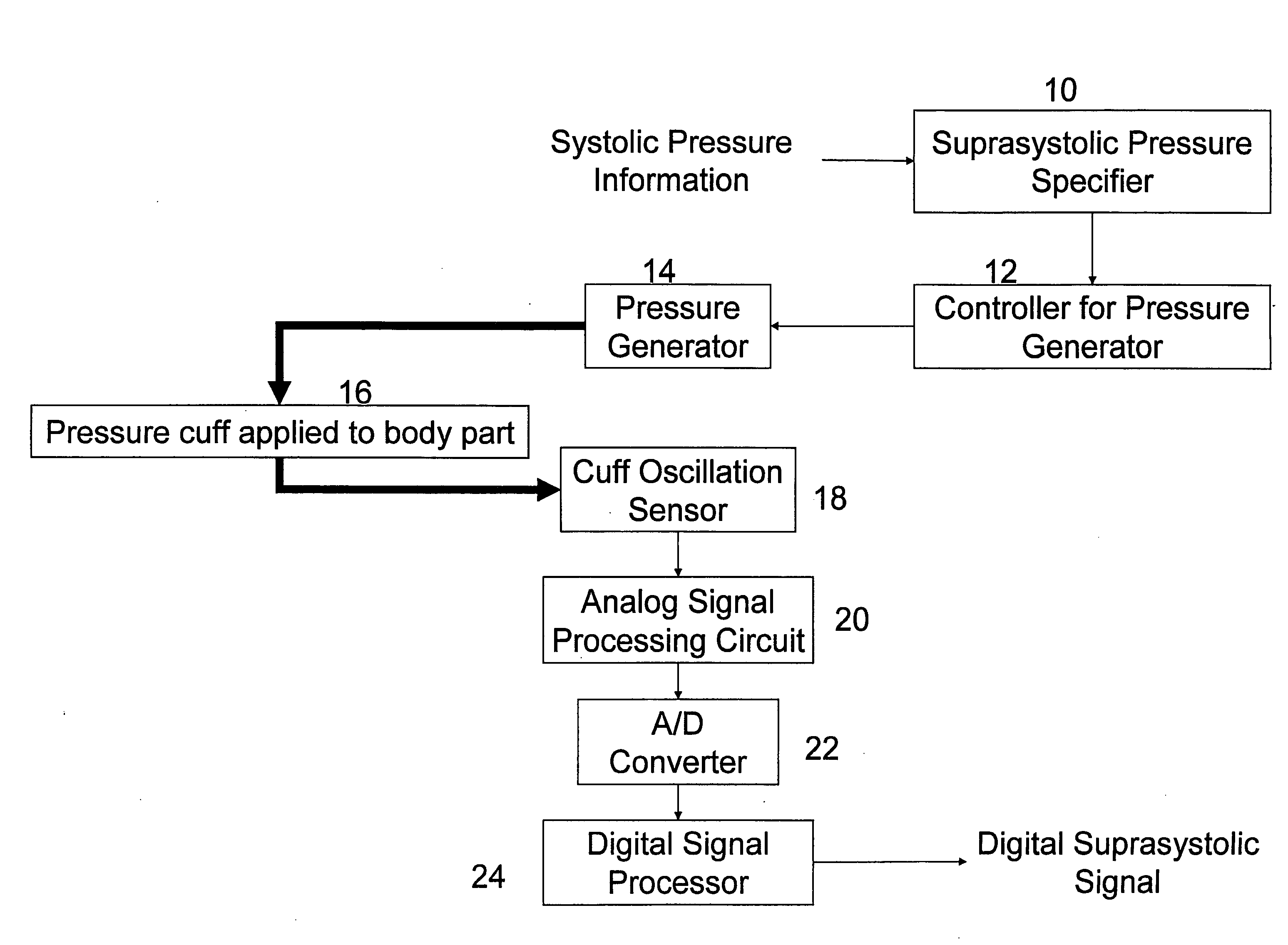
[0044]This invention concerns the measurement, processing and utility of blood pressure cuff oscillation signals recorded from a blood-pressure cuff applied to a body part, when the cuff pressure is above the systolic pressure, i.e., at supra-systolic pressures. The amplitude of such signals is typically much less than the total amplitude of cuff oscillation signals. However, these signals carry information directly related to the intra-arterial pressure waveform. Further, at supra-systolic pressures the artery is always in an occluded state, rendering the system being measured relatively constant. The cuff pulse pressure wave is therefore consistent and reproducible, and comparable between subjects.

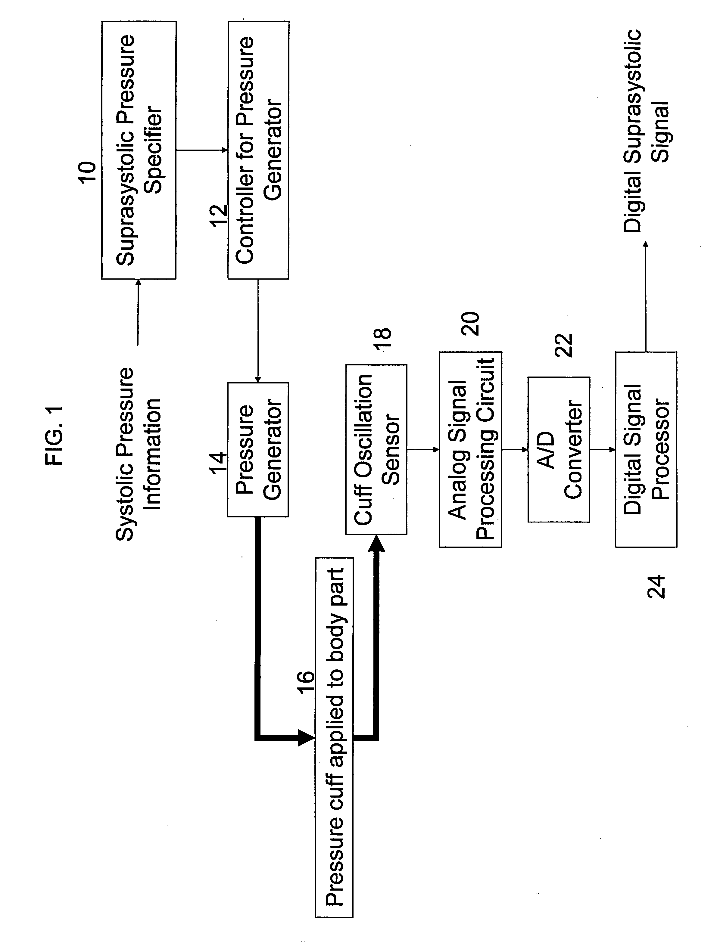
[0045]With reference to the drawings and in particular FIG. 1 initially, ...


PUM


Abstract

A method and apparatus are disclosed for the non-invasive measurement, processing and utility of blood pressure cuff oscillation signals from a blood pressure cuff applied to a body part when the blood pressure cuff pressure is at supra-systolic pressures. Oscillometric cardiac pulse waveforms associated with the peripheral artery are monitored during a plurality of cardiac ejection cycles while at supra-systolic pressure, and are measured pneumatically and transduced by an oscillometric pressure sensor. The analog signal is amplified, processed and digitized to provide a recordable waveform that can be analyzed to obtain information relating to the patient's cardiovascular status.

Description

CROSS-REFERENCE TO RELATED APPLICATIONS[0001]This application claims priority from U.S. provisional application No. 60 / 936,495, filed Jun. 20, 2007.[0002]This application also contains subject matter that is disclosed in U.S. Pat. No. 6,994,675, issued Feb. 7, 2006 and entitled “Non-Invasive Measurement of Supra-Systolic Signals,” U.S. patent application Ser. No. 11 / 358,283 filed Feb. 21, 2006 and entitled “System And Method For Non-Invasive Cardiovascular Assessment From Supra-Systolic Signals Obtained From A Wideband External Pulse Transducer In A Blood Pressure Cuff,” Publication No. US 2006 / 0224070 A1, (“the '070 publication”), and U.S. patent application Ser. No. 11 / 495,279, filed Jul. 28, 2006. The subject matter of this patent and these two applications are incorporated herein by reference.BACKGROUND OF THE INVENTION[0003]It has been known that the peripheral arterial pressure waveform carries information useful for evaluating a person's health and cardiovascular status and p...

Claims


Application Information

Patent Timeline
Patent Type & Authority Applications(United States)
IPC IPC(8): A61B5/0225
CPCA61B5/0225A61B5/02225
Inventor LOWE, ANDREWROLDAN, DANIEL NORBERTOSHARROCK, NIGEL E.
Owner PULSECOR LTD
Why Eureka
Try Eureka