Shape memory alloy actuator

a memory alloy and actuator technology, applied in the direction of motor/generator/converter stopper, dynamo-electric converter control, machine/engine, etc., can solve the problems of above-described conventional method, oscillation of moving body, and inability to suppress target resistance completely, so as to prevent oscillation

Active Publication Date: 2009-01-15
OLYMPUS CORP
View PDF3 Cites 33 Cited by
  • Summary
  • Abstract
  • Description
  • Claims
  • Application Information

AI Technical Summary

Benefits of technology

[0009]The present invention has been made in view of the above described situation and has as an object to provide a shape memory

Problems solved by technology

The above described conventional method, however, suffers from a problem as described, for example, in Kazuyuki Kodama et al.
Specifically, when the resistance of shape memory alloy is controlled to a predetermined target resistance by

Method used


Image

  • Shape memory alloy actuator
  • Shape memory alloy actuator
  • Shape memory alloy actuator

Examples


second embodiment

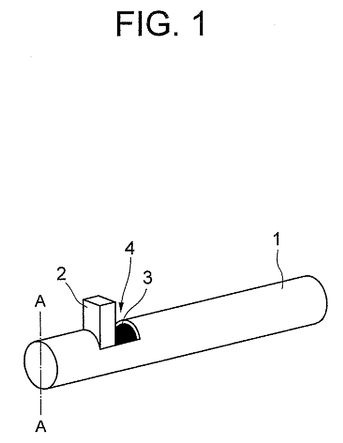
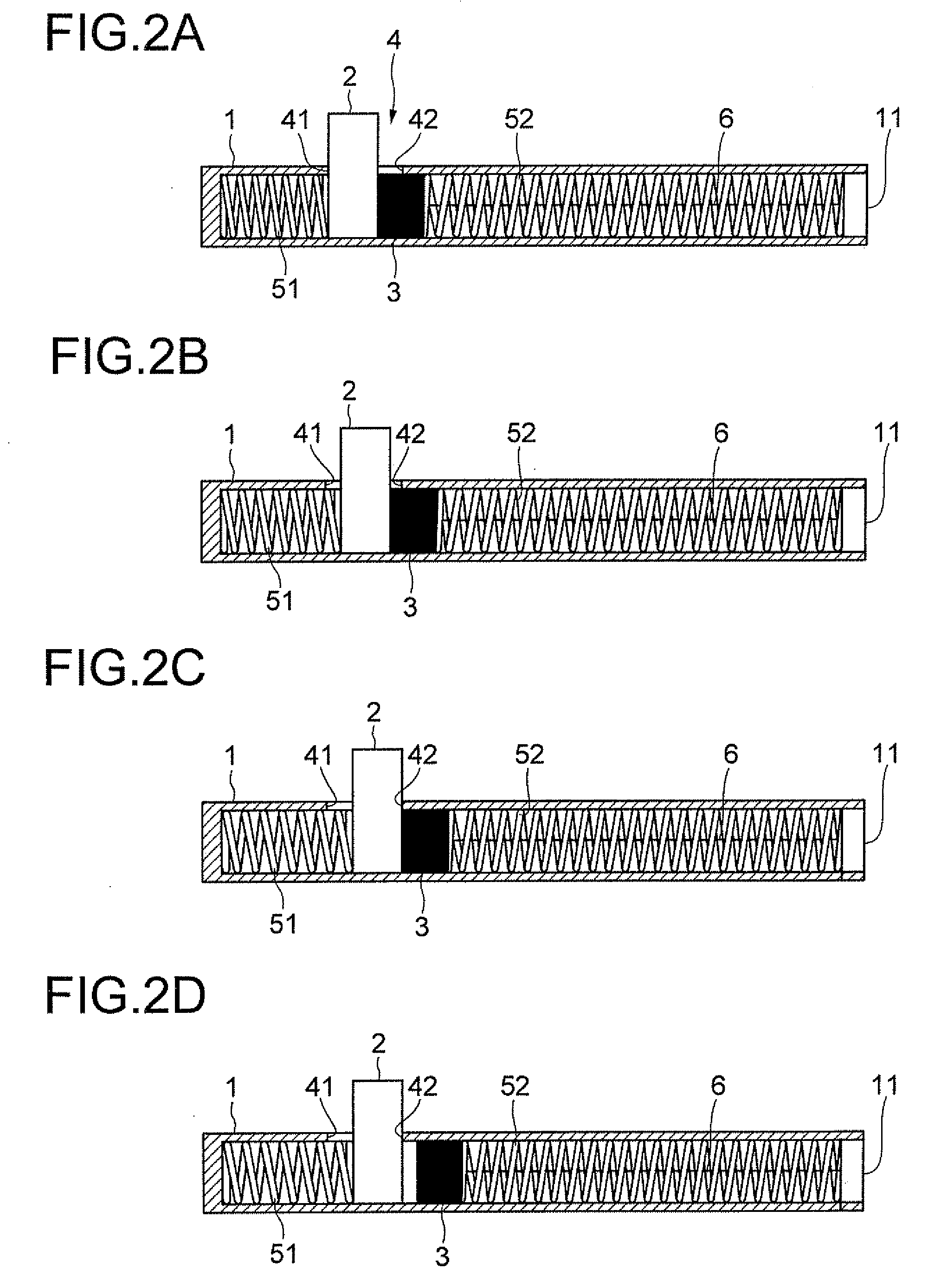
[0032]FIG. 3 is a perspective view of a shape memory alloy actuator according to a second embodiment of the present invention. FIG. 4 is a cross sectional view of the actuator taken along line B-B in FIG. 3. FIG. 5 is a cross sectional view taken along line C-C in FIG. 3. In the second embodiment, the portions same as those in the first embodiment will be denoted by the same reference signs to omit redundant description.

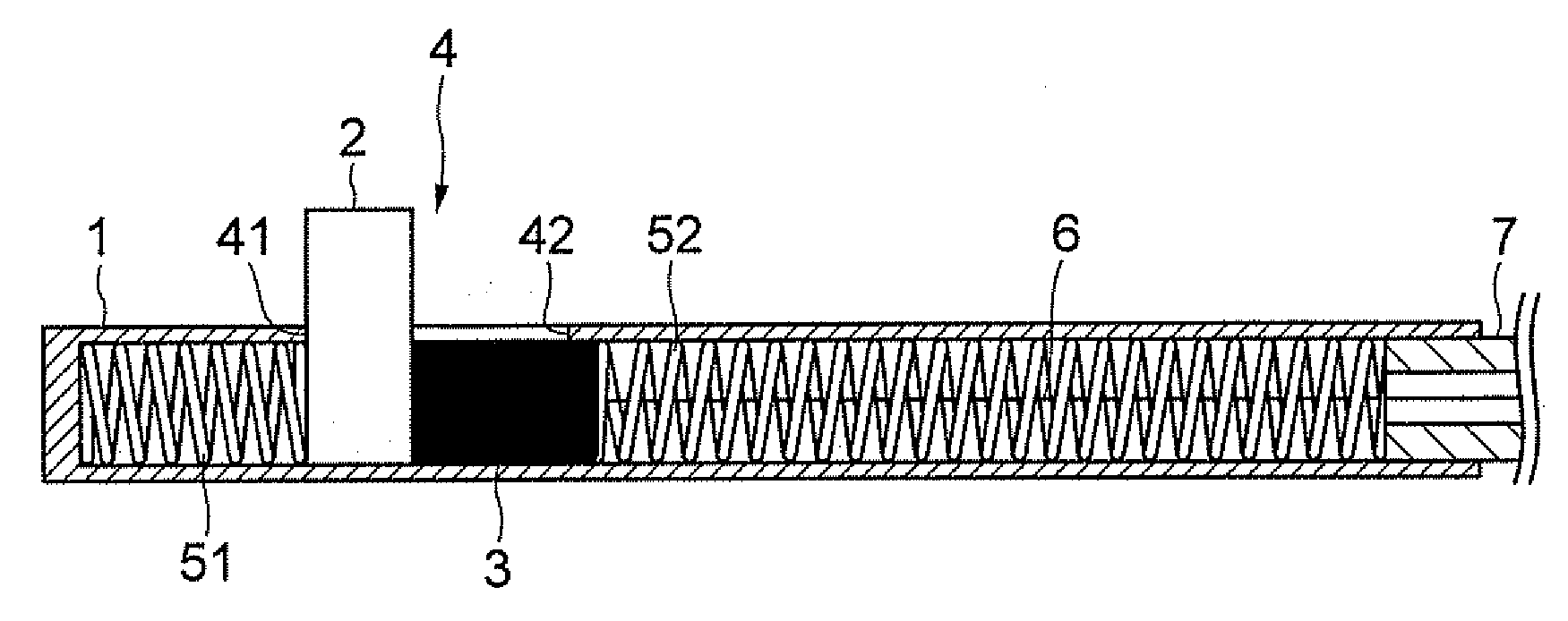
[0033]A part of a tube 7 is inserted into a cylinder 1 and fixed therein. A shape memory wire 6 passes through the interior of the tube 7. At the end of the tube 7 is provided a wire fixing member 8. One end of the shape memory wire 6 is fixed to the wire fixing member 8. The wire fixing member 8 is fixed to the end portion of the tube 7.

[0034]FIG. 4 is a cross sectional view taken along line B-B in FIG. 3. An end portion of the tube 7 is inserted into an end portion of the cylinder 1 and fixed thereto. One end of a bias spring 52 for a moving body pushing member is ...


PUM


Abstract

To provide a shape memory alloy actuator using a shape memory alloy that mechanically restrains a moving body in position to prevent oscillation, the actuator has a moving body pushing member adapted to be capable of abutting to the moving body, a bias spring for the moving body pushing member that exerts an external force on the moving body pushing member in the direction opposite to the direction of change in the shape of a shape memory wire caused by heating, a bias spring for the moving body that exerts an external force on the moving body in the direction same as the direction of change, a first stopper that restricts the movement of the moving body to a predetermined position upon cooling. One end of the shape memory wire is fixed, the other end is mechanically linked with the moving body pushing member. The moving body pushing member and the moving body are moved by deformation caused by heating, and the moving body and the moving body pushing member are separated, when the moving body is stopped at the position of the first stopper.

Description

CROSS-REFERENCE TO RELATED APPLICATION[0001]The present application is based upon and claims the benefit of priority from the prior Japanese Patent Application No. 2007-180833 filed on Jul. 10, 2007; the entire contents of which are incorporated herein by reference.BACKGROUND OF THE INVENTION[0002]1. Field of the Invention[0003]The present invention relates to a shape memory alloy actuator.[0004]2. Description of the Related Art[0005]A shape memory alloy changes its shape with phase transformation caused by a change in the temperature. Actuators that utilize deformation of such a shape memory alloy have characteristics that are advantageous in reducing the size and weight of the actuators.[0006]For example, Japanese Patent Application Laid-Open No. 57-141704 teaches to change the shape of a shape memory alloy by supplying an electrical current to it and to measures its resistance that changes with the change in the shape thereby controlling contraction and expansion of the shape mem...

Claims


Application Information

Patent Timeline
IPC IPC(8): F03G7/06
CPCF03G7/065
Inventor TAKAHASHI, MASAYA
Owner OLYMPUS CORP
Why Eureka
Try Eureka