
Gas leak detection apparatus and method

a technology for gas leak detection and detection methods, applied in the direction of instruments, fluid loss/gain rate measurement, fluid tightness measurement, etc., can solve the problems of difficult to distinguish between these two cases, the technique which measures the use time, and the long time it takes to shut off the gas, so as to prevent the mistaken detection of gas leakage, the probability of gas leakage is high, and the effect of accurate and rapid determination

Inactive Publication Date: 2009-01-15
TOSHIBA TOKO METER SYST
View PDF5 Cites 13 Cited by
  • Summary
  • Abstract
  • Description
  • Claims
  • Application Information

AI Technical Summary

Benefits of technology

[0010]The present invention was devised in order to resolve the problems of the prior art described above, an object thereof being to provide a gas leak detection apparatus and method whereby a gas leak can be detected rapidly, efficiently and accurately, and mistaken detection of a gas leak can be prevented, even when using an appliance which has been newly installed in a dwelling receiving a gas supply.
[0014]The present invention described above is devised by focusing on the fact that a flow volume pattern in which a flow volume occurs and then returns to zero relates not to a gas leak but rather to the use of an appliance, and when a flow volume pattern of this kind is newly extracted, then it is registered as characteristics data and is used in subsequent gas leak detection, thereby making it possible to prevent mistaken detection of a gas leak.
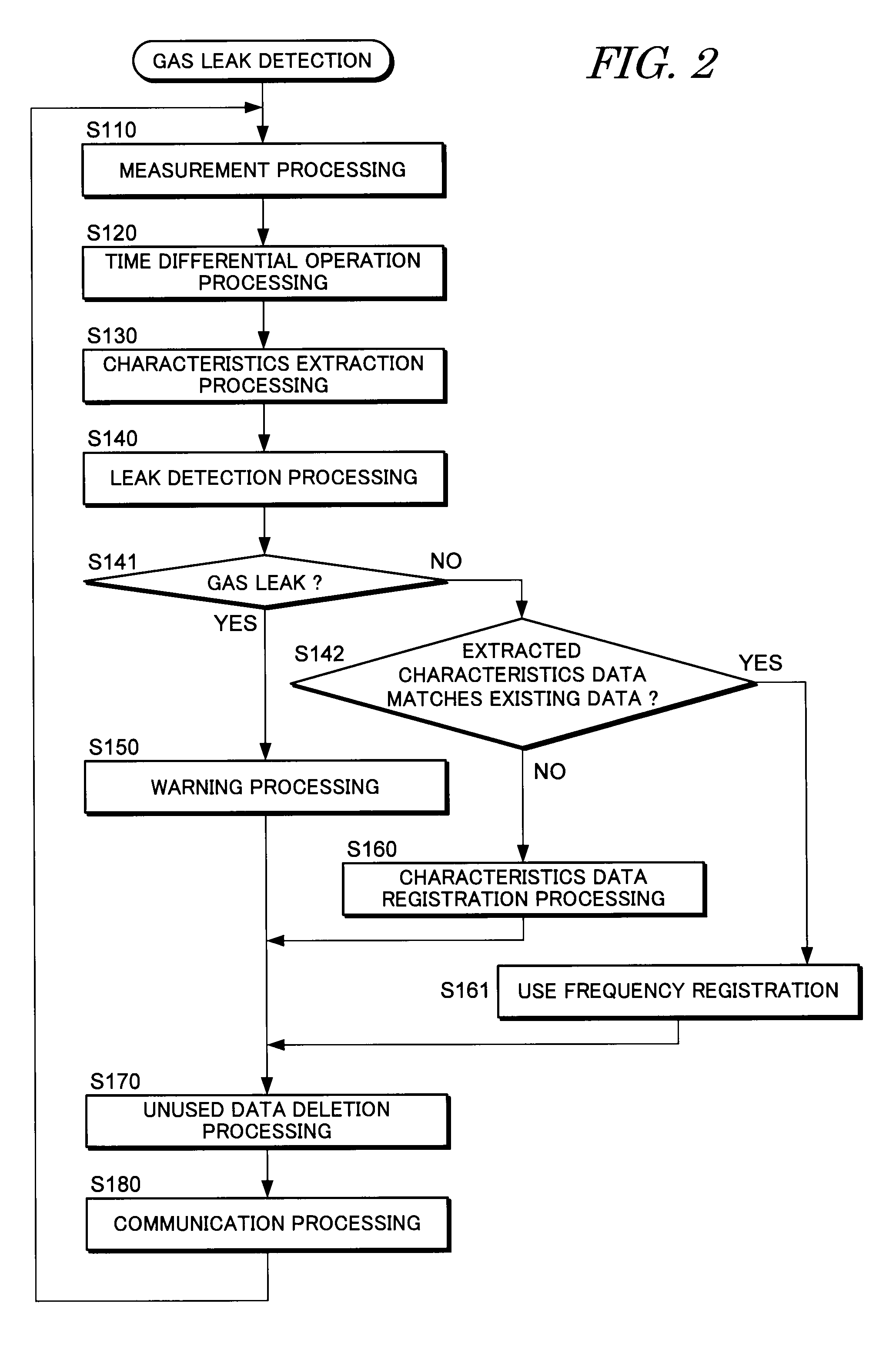
[0015]In the present invention, if the characteristics of a newly extracted flow volume pattern match the flow volume pattern of registered characteristics data, then this means that an appliance corresponding to that characteristics data is in use, and if they do not match, then it can be judged that there is a gas leak or that a new appliance is in use. Furthermore, if there is no matching, then it is judged whether or not there is a change in the flow volume or a change in the nozzle, on the basis of a combination of the instantaneous flow volume and the time differential value of the instantaneous flow volume, or the ratio between the flow volume and the square root of the pressure, and by this judgement, it can be determined accurately and rapidly whether there is a gas leak or whether an unregistered appliance is in use.
[0017]According to the present invention, it is possible to provide a gas leak detection apparatus and method whereby mistaken detection of a gas leak can be prevented even when using an appliance which has been newly installed in a dwelling receiving a gas supply, and whereby a gas leak can be detected rapidly, efficiently and accurately.

Problems solved by technology

However, as shown in FIG. 7, a technique which measures the use time and compares same with a safe continuous use time is problematic in that it takes a long time to shut off the gas, even in the event of a gas leak.
However, even if a technique such as this is used, since a state of no change in the flow volume range or pattern continues both in the case of a gas leak and in the case of continuous use of a gas appliance which is not fitted with a governor (pressure regulator), such as cooking stove, then it has been difficult to distinguish between these two cases.
In particular, when using an appliance which has been newly installed in a dwelling receiving a gas supply, since there is no data for comparison in relation to that appliance, then there has been a possibility of a gas leak being detected mistakenly.

Method used


Image

  • Gas leak detection apparatus and method
  • Gas leak detection apparatus and method
  • Gas leak detection apparatus and method

Examples


embodiment

Composition of Embodiment

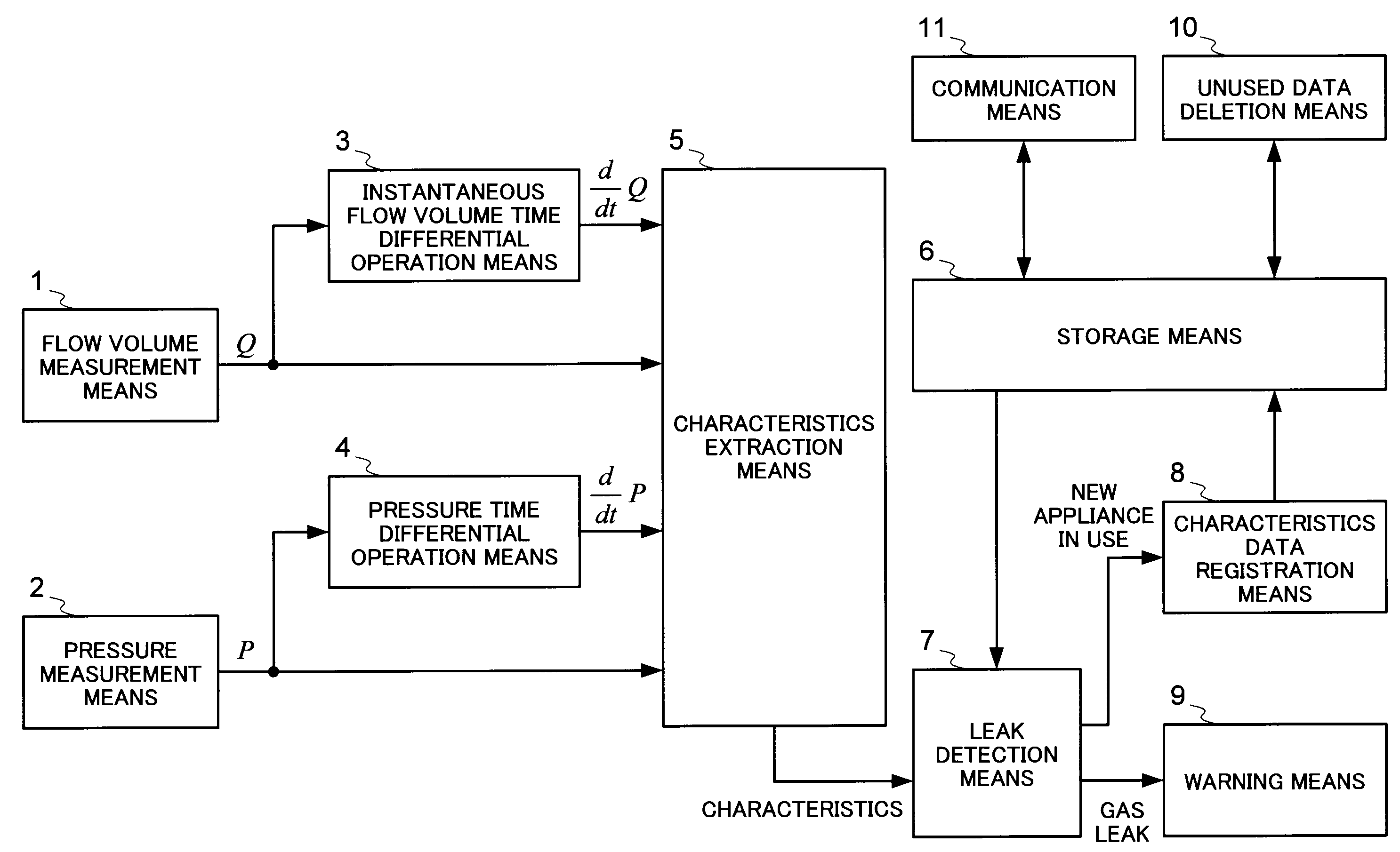
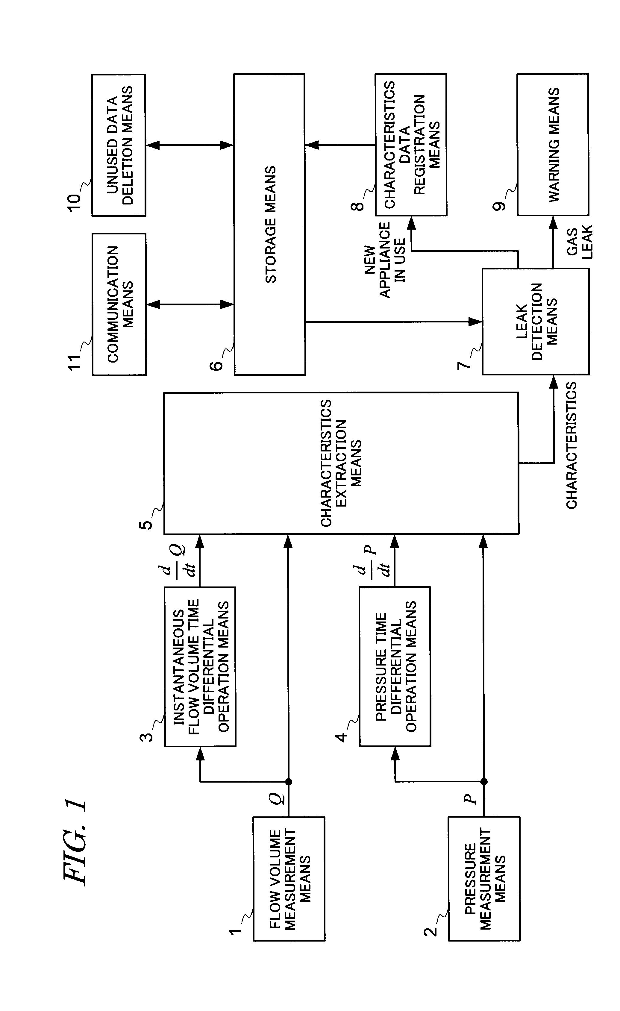
[0025]FIG. 1 is a functional block diagram showing the composition of a gas leak detection apparatus according to an embodiment to which the present invention has been applied. As shown in FIG. 1, the gas leak detection apparatus according to the present embodiment is composed of a flow volume measurement means 1, a pressure measurement means 2, an instantaneous flow volume time differential operation means 3, a pressure time differential operation means 4, a characteristics extraction means 5, a storage means 6, a leak detection means 7, a characteristics data registration means 8, warning means 9, an unused data deletion means 10 and a communication means 11. The details of the means 1 to 11 are as follows.

[0026]The flow volume measurement means 1 is a means for measuring the instantaneous flow volume Q of the gas flowing inside a gas supply flow channel (gas pipe). It is possible to use various types of measurement means for the flow volume measurement me...


PUM


Abstract

According to the present invention, mistaken detection of a gas leak can be prevented even when using an appliance which has been newly installed in a dwelling receiving a gas supply, and whereby a gas leak can be detected rapidly, efficiently and accurately. The characteristics extraction means 5 extracts characteristics of a gas flow including a combination of the instantaneous flow volume data and the instantaneous flow volume time differential value, on the basis of the data obtained by the flow volume measurement means 1, pressure measurement means 2, instantaneous flow volume time differential operation means 3 and pressure time differential operation means 4. The leak detection means 7 compares the characteristics data for respective types of gas appliance or for a gas leak registered in the storage means 6 with the characteristics extracted by the characteristics extraction means 5, and if a matching is not achieved, further judges whether there is a flow volume variation or nozzle variation, and whereby it judges whether there is a gas leak or whether an unregistered appliance is in use. If occurrence of a gas leak, the warning means 9 issues a warning. If an unregistered appliance is in use, the characteristics data forming the basis of the judgment is registered as a new characteristics data in the storage means 6 by the characteristics data registration means 8.

Description

BACKGROUND OF THE INVENTION[0001]1. Field of the Invention[0002]The present invention relates to a gas leak detection apparatus and detection method used in a gas meter or the like which is disposed in a gas supply line to a domestic dwelling and has a gas flow meter, and more particularly it relates to technology which enables the provision of higher advanced safety functions and services by detecting the presence of a gas leak during occurrence and continuation of the flow volume by a gas supply.[0003]2. Description of the Related Art[0004]A gas meter incorporating a gas flow meter is installed at the inlet port of the gas supply line to a domestic dwelling. The gas meter measures the gas flow volume passing through the gas supply line, and the measured gas flow volume is used to calculate a periodic gas billing amount. In addition to basic functions, such as measuring the gas flow volume, the gas meter also has a safety function for shutting off the gas supply when an abnormal st...

Claims


Application Information

Patent Timeline
IPC IPC(8): G01M3/28
CPCF17D5/02G01M3/26F17D3/01G08C2200/00
Inventor NAKANO, KENJISAMEDA, YOSHITOTAKANOHASHI, YUKIOUYAMA, HIROTOISHINO, MASAAKI
Owner TOSHIBA TOKO METER SYST
Learn More