A-frame barricade

a barricade and frame technology, applied in the direction of roads, roads, constructions, etc., can solve the problems of reducing the effect of wind and requiring the barricade to be walked along, and achieve the effect of high efficiency, compact storage, and high specific gravity

Inactive Publication Date: 2009-01-15
LUND JOHN IVER
View PDF11 Cites 9 Cited by
  • Summary
  • Abstract
  • Description
  • Claims
  • Application Information

AI Technical Summary

Benefits of technology

[0012]In accordance with the invention, recesses are formed in the outsides of legs of A-frame members to provide pockets into which elongated weight cartridges are placed to be securely held to the leg portions. Preferably, each cartridge engages a rear wall of a leg, an outer wall of the leg and an intermediate wall spaced outwardly from an inner wall of the leg. The cartridge acts in compression between the outer wall and the intermediate wall to oppose bending of the leg. For additional strength and rigidly, angularly extending walls are provided the intermediate wall and the inner wall, also between outer and inner walls above the weight cartridge. The weights of the cartridges are used to resist tilting movement of the barricade and to achieve stability with a high degree of efficiency. The distance between a fulcrum point at the lower end of each leg porti...

Problems solved by technology

The addition of the aforementioned weight cartridges substantially reduces the effect of winds as to tipping over and movement of the barricades.
Howe...

Method used


Image

  • A-frame barricade
  • A-frame barricade
  • A-frame barricade

Examples


Embodiment Construction

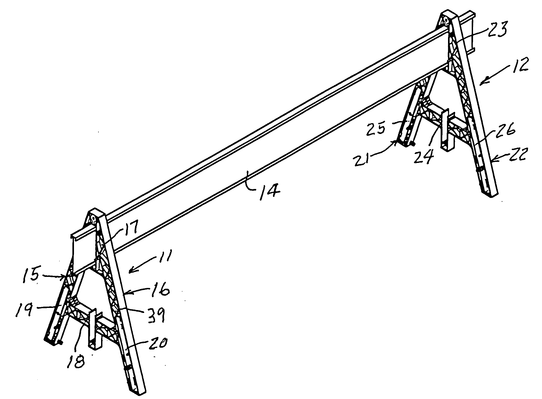
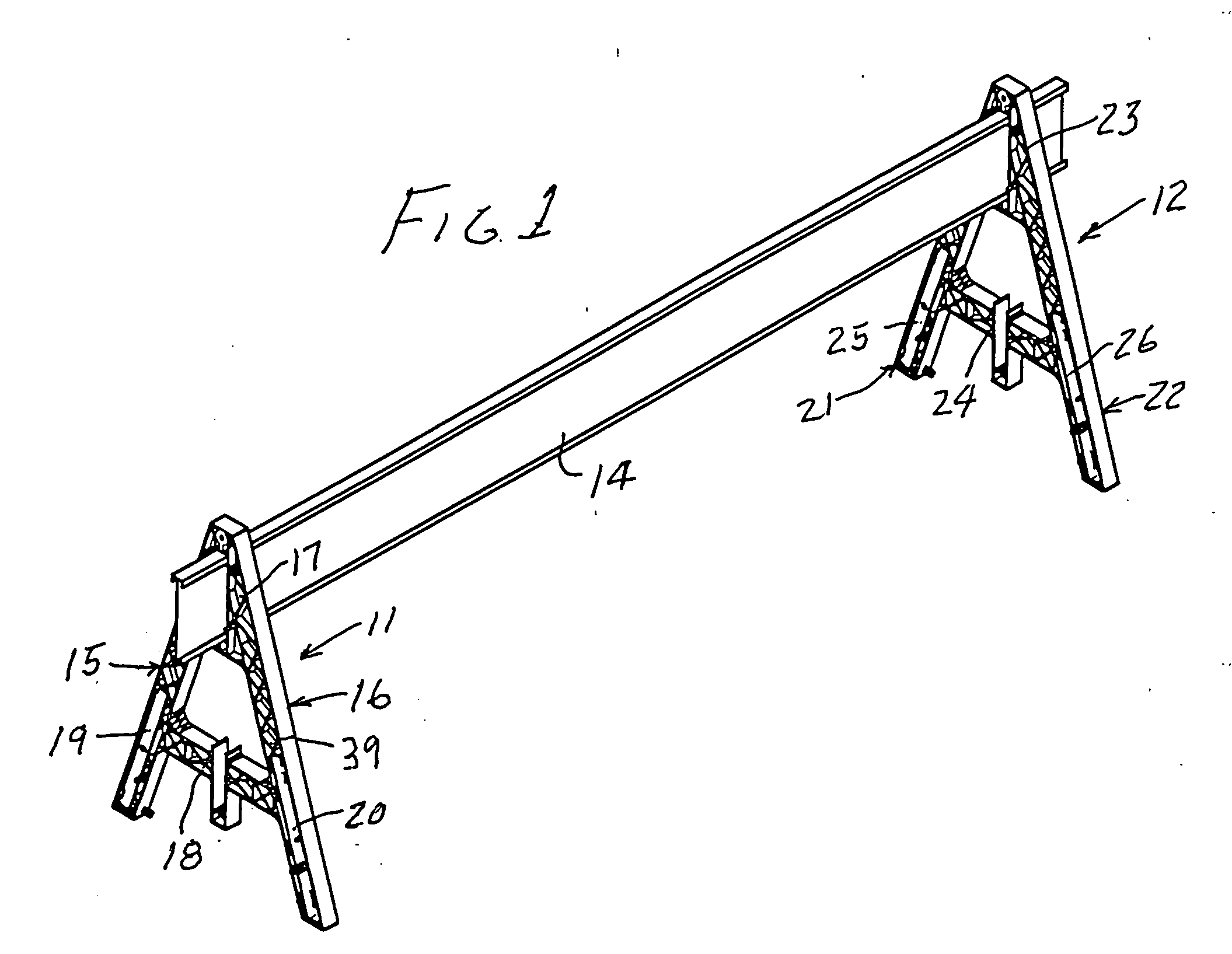
[0023]In FIG. 1, reference numeral 10 generally designates an A-frame type of barricade constructed in accordance with the invention. The barricade 10 includes two A-frame members 11 and 12 shown supporting an elongated beam 14. The member 11 includes two legs 15 and 16 which extend angularly upwardly toward each to meet an apex portion 17 which is formed with an opening through which one end of the supported member 14 extends. The member 11 also has a portion 18 that extends between and connects portions of the legs 15 and 16 at an intermediate level. The member 11 thus has an overall shape like that of the letter A.

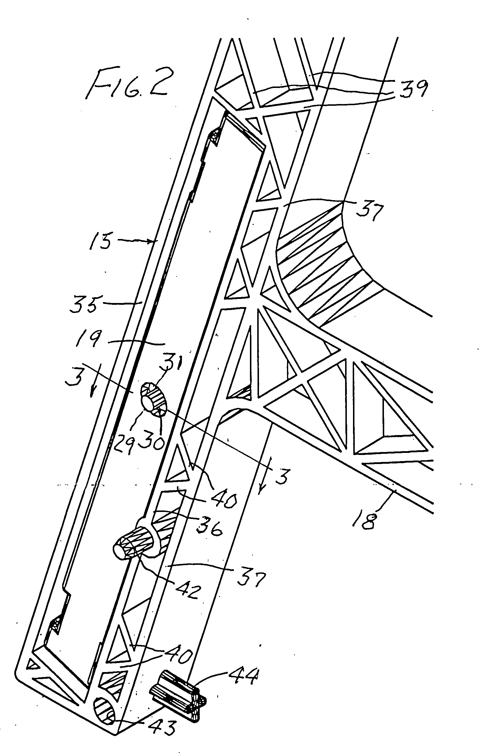
[0024]In accordance with the invention, the legs 15 and 16 are formed with recesses which provide pockets for receiving two elongated weight cartridges 19 and 20. Through the force of gravity acting thereon, the cartridges 19 and 20 function to resist tilting movement of the members 11 and 12. Thus cartridge 19 in leg 15 develops a stabilizing torque equal to the produc...


PUM


Abstract

A pair of A-frame members of molded plastic support an elongated beam extending through openings in apex portions thereof. Pockets are provided in the outsides of two legs of each A-frame member into which elongated weight cartridges are placed to be securely held to the legs. The legs and pockets are so formed that with a low volume and weight, a high strength and rigidity of the legs is achieved, a substantial contribution being made by the weight cartridges. The weights of the cartridges are used to resist tilting movement of the barricade and to achieve stability with a high degree of efficiency. The weight cartridges are preferably blow-molded plastic tubes filed with slag or sand and most preferably are interchangeable with cartridges currently in use in other applications. For additional stability, the legs of each A-frame member may be secured to an elongated member, to a plastic tube mounted there-between and/or to a blow-molded panel that is adapted to be filled with a weighty material and face in a longitudinal direction. Also, for additional strength and stability, elongated beams may be hung on lower portions of legs of the pair of A-frame members.

Description

CROSS-REFERENCE TO RELATED APPLICATION[0001]Applicant claims the priority benefit of Provisional Application No. 60 / 937,777 filed Jun. 29, 2007 and entitled “A-FRAME BARRICADE”.[0002]The invention disclosed herein is not the result of any federally sponsored research or development activities.BACKGROUND OF THE INVENTION[0003]Barricade structures of the prior art include saw-horse and A-frame types of structures. Saw-horse structures typically include two units that are pivotally connected for movement between a folded condition against each other and an operative condition in inverted V-relation. In an early type of saw-horse structure, many of which are still in current use, each unit is in the form of a subassembly with wood panels secured to a pair of metal legs with bolts connecting the legs to form the pivotal connection. The Nunn U.S. Pat. No. 3,015,804 issued Jan. 2, 1962 shows a barricade including spaced apart leg units each consisting of a pair of hingedly connected legs a...

Claims


Application Information

Patent Timeline
IPC IPC(8): E01F13/02
CPCE01F13/02
Inventor LUND, JOHN IVER
Owner LUND JOHN IVER
Why Eureka
Try Eureka