Elevator drive assembly including a capacitive energy storage device

a technology of capacitive energy storage and drive assembly, which is applied in the direction of elevators, climate sustainability, sustainable buildings, etc., can solve the problems of affecting the performance of batteries, the specific energy of super-capacitors is low, and the energy storage of elevators is not good

Inactive Publication Date: 2009-01-15
OTIS ELEVATOR CO
View PDF4 Cites 18 Cited by
  • Summary
  • Abstract
  • Description
  • Claims
  • Application Information

AI Technical Summary

Problems solved by technology

For example, batteries have the disadvantages associated with a relatively long time period for charging and discharging the battery, a relatively short life cycle and temperature dependence that affects the battery's performance.
Super-capacitors, however, have a low specific energy when compared to a battery.
Previous attempts to achieve a good mix of battery and super-capacitors for energy storage in an elevator system has not proven satisfactory.

Method used


Image

  • Elevator drive assembly including a capacitive energy storage device
  • Elevator drive assembly including a capacitive energy storage device

Examples


Embodiment Construction

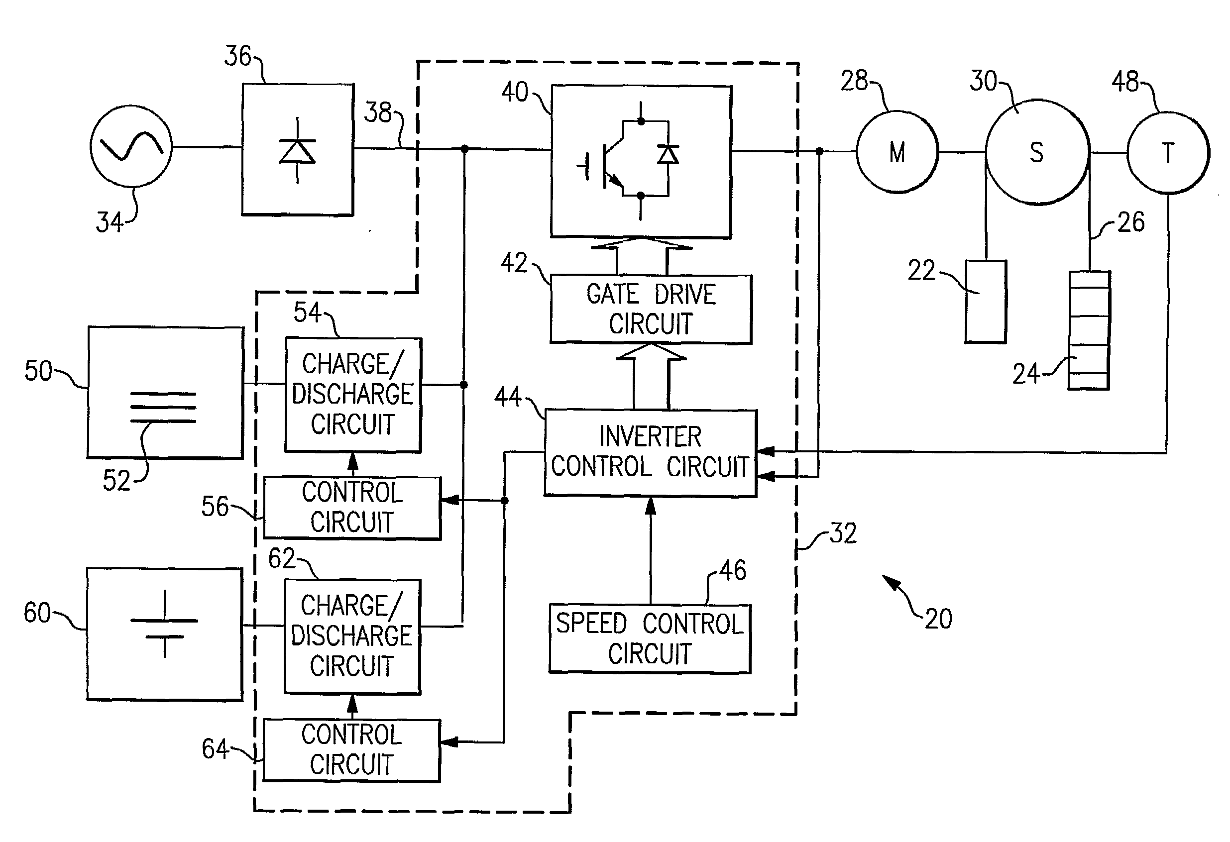
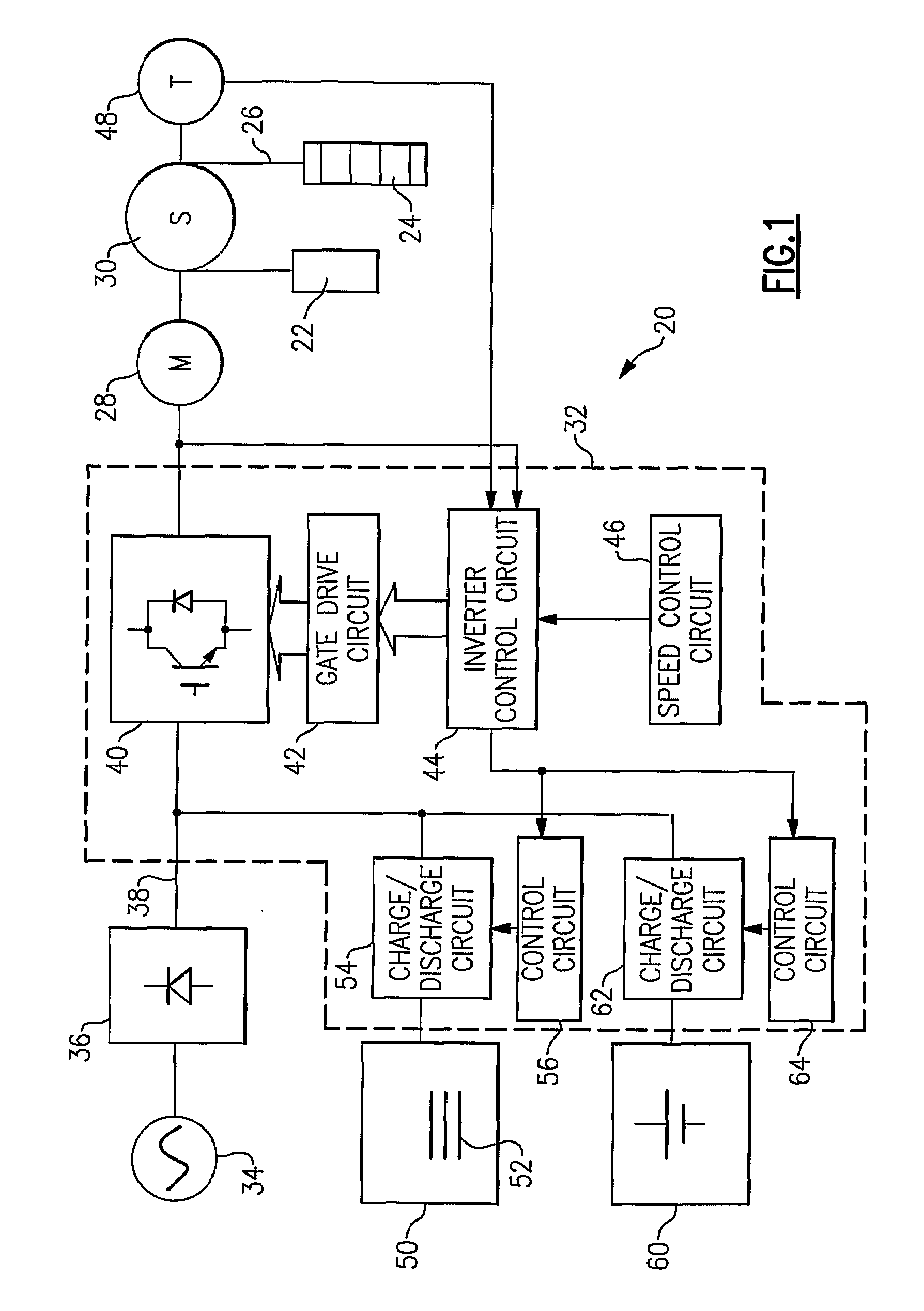
[0010]FIG. 1 schematically shows an elevator drive assembly 20 for providing desired movement of an elevator car 22. In the illustrated example, the elevator system is a traction-based system where the elevator car 22 is associated with a counterweight 24 through conventional roping 26. An electric motor 28 provides rotation to a traction sheave 30 to cause movement of the roping 26 and the car 22 and counterweight 24.

[0011]A drive 32 controls power supply to the motor 28 from a power source 34 such as a utility grid or a variable frequency ac source driven by a prime mover. In this example, the motor 28 is an AC induction motor and a rectifier 36 is provided between the power source 34 and the motor 28. One example includes a permanent magnet motor.

[0012]The drive 32 in this example includes a DC bus 38, at least one converter IGBT 40, an appropriate gate drive circuitry portion 42, an inverter control portion 44 and a speed control circuit 46. The just-mentioned portions of the dr...


PUM


Abstract

An elevator drive assembly (20) includes a motor (28), drive (32) and a capacitive energy storage device (50). In a disclosed example, the capacitive energy storage device (50) comprises at least one nano-gate capacitor (52). The disclosed example has unique energy storage capabilities provided by the presence of the at least one nano-gate capacitor.

Description

FIELD OF THE INVENTION[0001]This invention generally relates to elevators. More particularly, this invention relates to elevator drive assemblies including power consumption control.DESCRIPTION OF THE RELATED ART[0002]Elevator systems include a drive assembly for providing the desired movement of the elevator car between landings within a building, for example. Most drive assemblies include an electric motor that generates the forces necessary to achieve the desired elevator car movement and a drive that controls power supply to the motor. In the case of a traction-based elevator, the electric motor provides rotation to a traction sheave that moves roping that is used to suspend an elevator car and counterweight, for example.[0003]It is known to attempt to reduce peak power consumption by the electric motor and elevator drive assembly by providing an electrical energy storage. Proposed arrangements include batteries or traditional capacitors as an energy storage device. U.S. Pat. No...

Claims


Application Information

Patent Timeline
Patent Type & Authority Applications(United States)
IPC IPC(8): B66B1/06
CPCY02B50/142B66B1/302Y02B50/00
Inventor VEDULA, SASTRY V.THOMPSON, MARK S.
Owner OTIS ELEVATOR CO
Why Eureka
Try Eureka