Eureka AIR delivers breakthrough ideas for toughest innovation challenges, trusted by R&D personnel around the world.

Ion Control Sensor

a technology of ion control and liquid crystal substrate, which is applied in the direction of electrostatic field measurement, instruments, measurement devices, etc., can solve the problems of reducing the accuracy of liquid crystal substrate 0 [v], requiring more time and power, and limiting the improvement of static electricity removal precision, etc., to achieve high efficiency, high precision, and low cost

Inactive Publication Date: 2009-01-15
HUGLE ELECTRONICS
View PDF3 Cites 8 Cited by
  • Summary
  • Abstract
  • Description
  • Claims
  • Application Information

AI Technical Summary

Benefits of technology

[0014]With the above configuration, the present invention realizes a static electricity removal device with high precision and high efficiency, capable of detecting an ion balance between positive and negative ions generated by the static electricity removal device and a surface potential of a target of static electricity removal using a single ion control sensor.
[0015]Further, the present invention can be achieved only by attaching a conductive cap to a potential detector of an existing surface potential measuring probe via an insulating member and can be provided at a low cost with a remarkably simple configuration.

Problems solved by technology

However, a static electricity removing operation not required originally needs to be carried out and thus more time and power are required.
In the prior art described in Japanese Patent No. 3522586, the number of ions that reach the liquid crystal substrate is controlled in accordance with the electric field strength corresponding to the amount of electrostatic charge of the liquid crystal substrate, and therefore, there is a limit in improving precision of the static electricity removal, and for example, it is difficult to maintain the liquid crystal substrate precisely at ±0 [V].
Since it is necessary to provide a large-sized grid electrode plate etc. in order to cover a space between a plurality of discharge electrode needles arranged in the static electricity removal device and the liquid crystal substrate, there is a problem in that components are upsized, and therefore, the entire device is upsized and its cost is raised.

Method used


Image

  • Ion Control Sensor
  • Ion Control Sensor
  • Ion Control Sensor

Examples


Embodiment Construction

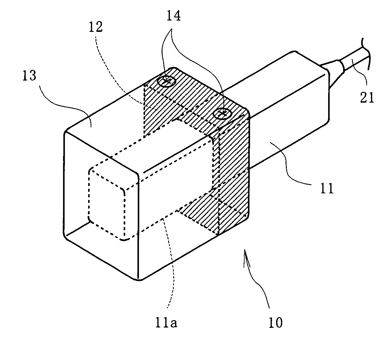
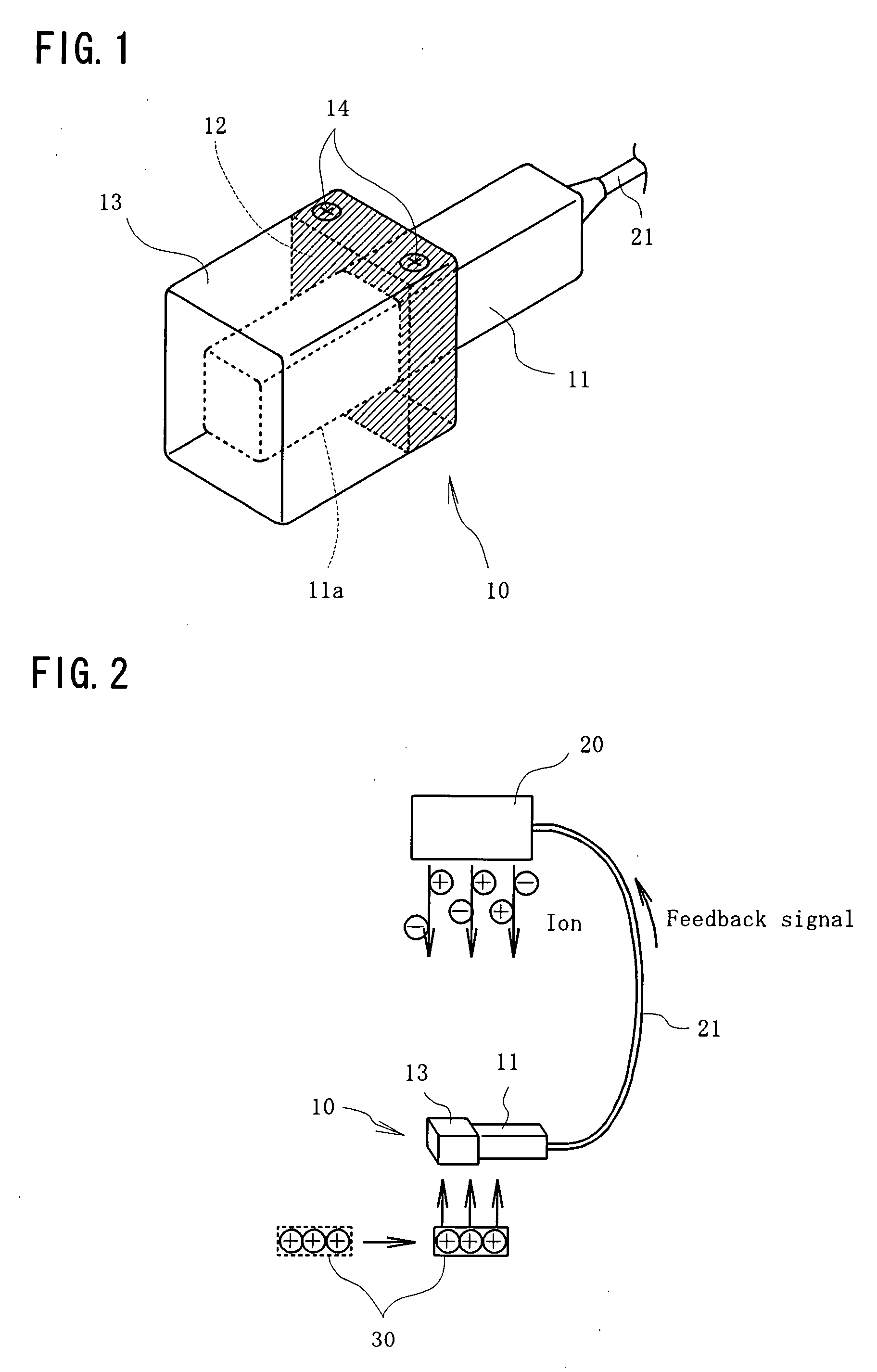
[0019]Best modes for carrying out the present invention will be explained below with reference to the drawings. FIG. 1 is a perspective view of an ion control sensor 10 according to an embodiment.

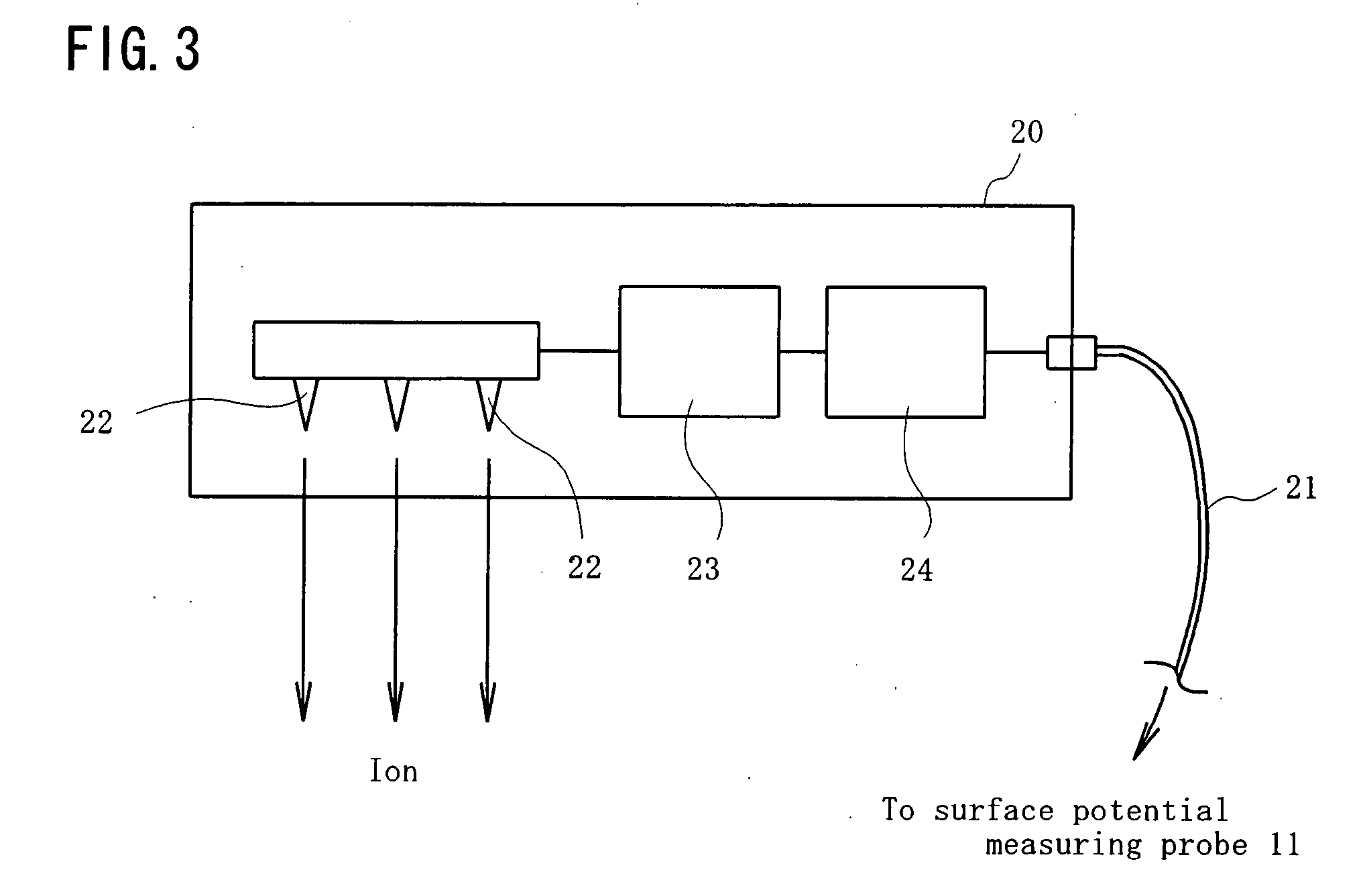
[0020]In FIG. 1, reference number 11 denotes a rectangular rod-like surface potential measuring probe, such as a so-called tuning fork-type or vibrating reed-type surface potential measuring apparatus. This probe 11 is capable of measuring a surface potential of a target of static electricity removal without contact. The principle of surface potential measurement by the probe 11 is not limited in particular. The probe 11 is connected to a static electricity removal device 20, to be described later, via a cable 21.

[0021]Substantially at the center of the surface potential measuring probe 11 in the longitudinal direction, a hollow square-shaped insulating member 12 made of synthetic resin etc. is fixed and a bottomed rectangle-cylindrical cap 13 made of conductive material is attached with sc...


PUM


Abstract

A static electricity removal device that removes static electricity by supplying positive and negative ions to a target of static electricity removal, comprising a surface potential measuring probe that measures a surface potential of the target of static electricity removal, wherein a potential detector (11a) that constitutes a surface potential measuring probe (11) and a conductive cap (13) placed so as to surround the potential detector (11a) in a non-contact state are provided and a potential generated in the cap (13) by charges of a target of static electricity removal (30) or ions supplied from a static electricity removal device (20) is detected by the potential detector (11a) and sent out to a control circuit (24) within the static electricity removal device (20) as a feedback signal. According to the present invention, a remarkably simple configuration makes it possible to detect an ion balance and a charged potential of the target of static electricity removal, thereby contributing to improvement in static electricity removal performance of an ionizer.

Description

TECHNICAL FIELD[0001]The present invention relates to an ion control sensor that can detect both an ion balance between the numbers of positive and negative ions generated by a static electricity removal device and a charged potential of a target of static electricity removal.BACKGROUND ART[0002]Conventionally, a static electricity removal device that variably controls a voltage to be applied to a discharge electrode needle in accordance with a quantity of electrostatic capacity and a surface potential of a target of static electricity removal is described, for example, in Japanese Patent Application Laid-open No. H11-345697 ([0010] to [0017], FIG. 1, etc.)[0003]The static electricity removal device has at least one discharge electrode needle that causes corona discharge to occur on a target of static electricity removal by applying a voltage, a surface potentiometer that continuously measures a surface potential of the target of static electricity removal, an arithmetic processor t...

Claims


Application Information

Patent Timeline
IPC IPC(8): G01R29/12
CPCG01R19/0061G01R29/24G01R29/12
Inventor NAKAJIMA, YOMATSU
Owner HUGLE ELECTRONICS
Why Eureka
Eureka Blog
Learn More