Distortion compensation apparatus

a compensation apparatus and distortion compensation technology, applied in the direction of amplifier modifications to reduce non-linear distortion, digital transmission, baseband system details, etc., can solve the problems of large scale, low efficiency of front-end distortion compensation scheme, and high cost of feedforward scheme, so as to achieve more effective distortion compensation

Inactive Publication Date: 2009-01-15
KOKUSA ELECTRIC CO LTD
View PDF7 Cites 5 Cited by
  • Summary
  • Abstract
  • Description
  • Claims
  • Application Information

AI Technical Summary

Benefits of technology

[0044]As has been explained above, in accordance with the distortion compensation apparatus of the present invention, in order to generate a distortion to compensate for a distortion generated by an amplifier, the nonlinear circuit having the input / output saturation characteristic is used. Thus when compared with the case where only the nonlinear circuit having the input / output expansion characteristic is used, for example, the present invention can achieve more effective distortion compensation.

Problems solved by technology

The feedforward scheme has a merit that a high amount of distortion compensation can be realized with stable distortion compensation, but also has a demerit that a circuit scale becomes large and the cost of the feedforward scheme becomes higher than that of the front-end distortion compensation scheme with a bad efficiency.
Meanwhile, the analog front-end distortion compensation method has a merit that a circuit scale becomes small with a good economy, but also has a demerit that an amount of distortion compensation becomes lower than the compensation amounts of the other distortion compensation methods.
The digital front-end distortion compensation method has a merit that a high amount of distortion compensation can be realized with a good power efficiency and a good productivity, but also has a demerit that a circuit scale becomes large and the cost becomes higher than that of the analog arrangement.

Method used


Image

  • Distortion compensation apparatus
  • Distortion compensation apparatus
  • Distortion compensation apparatus

Examples


Embodiment Construction

[0055]Embodiments of the present invention will be explained by referring to the accompanied drawings.

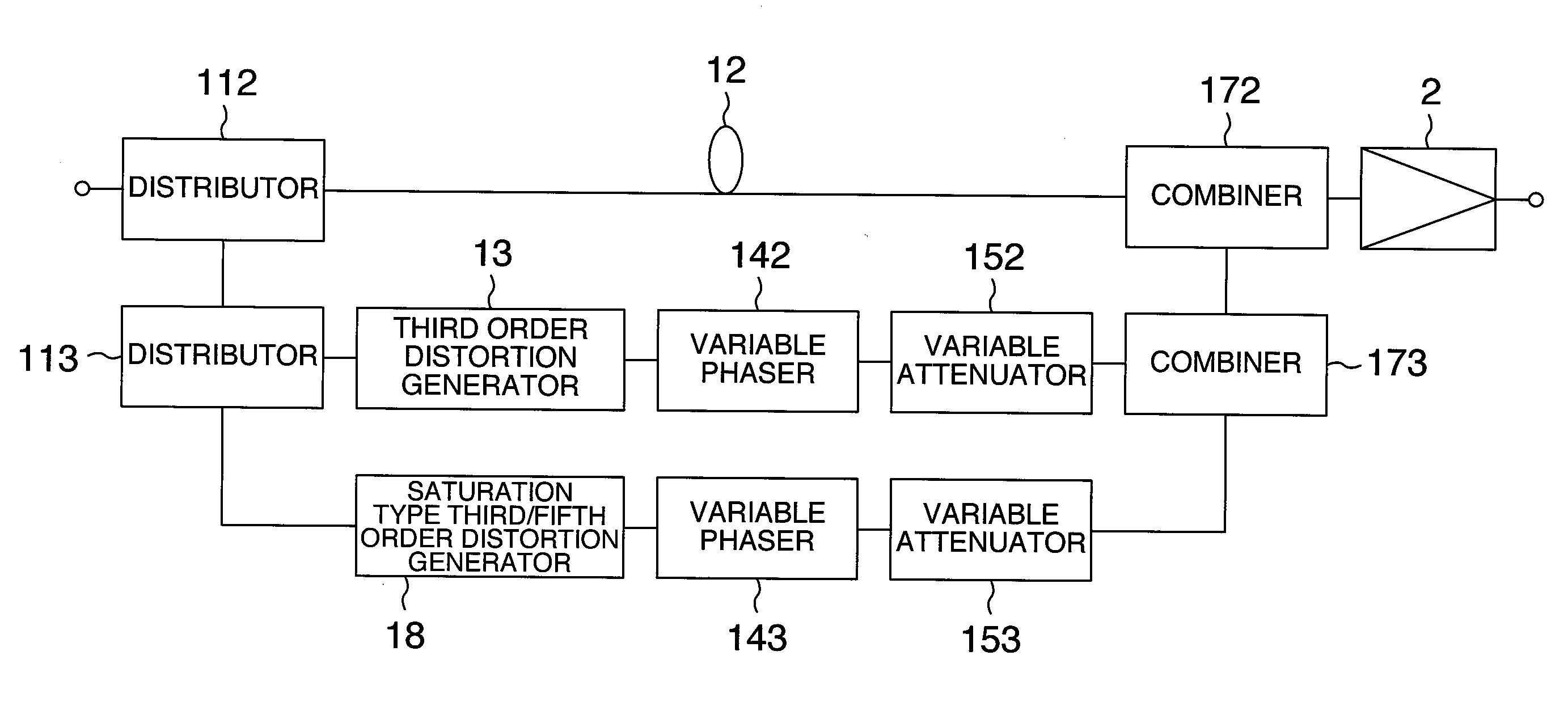
[0056]In the present embodiments, explanation will be made as to the circuit configuration of a distortion compensation apparatus for reducing a distortion generated in an amplifier used in a base station amplification device or a relay unit in a wireless system and also as to its control method. More in particular, explanation will be made as to a distortion compensation apparatus which uses a front-end distortion compensation circuit as a distortion compensation scheme circuit, has a high compensation with an inexpensive circuit configuration, and achieves stable control.

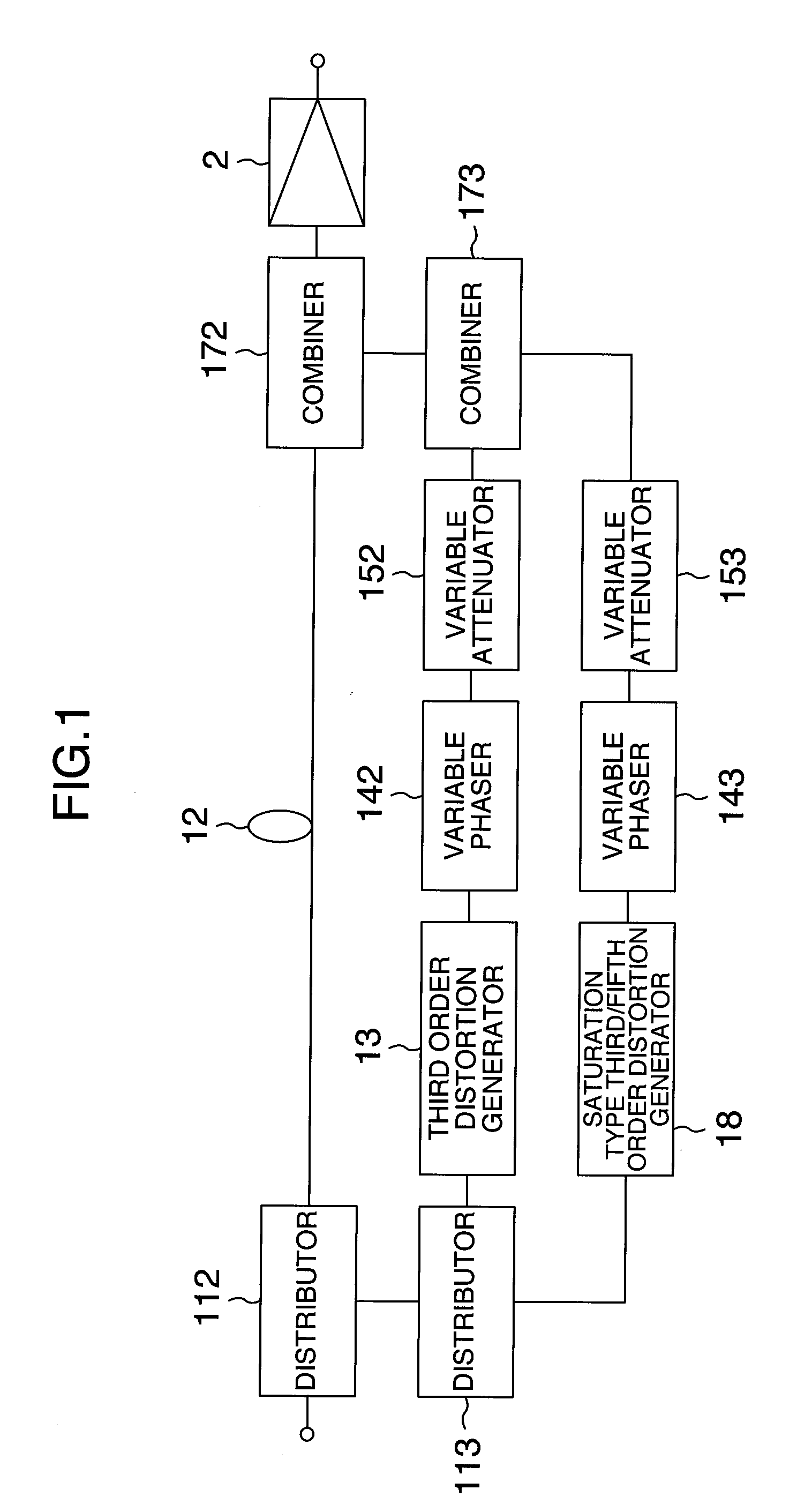
[0057]For the convenience of explanation, similar constituent elements in FIGS. 1, 3, 6, 7, and 9 are denoted by the same reference numerals. The arrangement or configuration of these drawings are illustrated merely as an example, and various sorts of arrangements or configurations may be employed.

[0058]FIG. 1 sho...


PUM


Abstract

A distortion compensation apparatus includes distortion generating means for generating distortions to compensate for a distortion generated in an amplifier 2. The distortion generating means includes a nonlinear circuit 13 having an input/output expansion characteristic as a circuit which generates a distortion of the lowest odd order as a compensation target and also includes a nonlinear circuit 18 having an input/output saturation characteristic as a circuit which generates a distortion of another odd order as a compensation target.

Description

INCORPORATION BY REFERENCE[0001]The present application claims priority from Japanese application JP2007-112732 filed on Apr. 23, 2007, the content of which is hereby incorporated by reference into this application.BACKGROUND OF THE INVENTION[0002]The present invention relates to distortion compensation apparatuses and more particularly, to a distortion compensation apparatus which effectively compensates for a distortion.[0003]As typified by a cellar phone, in these days, such a system as to utilize wireless communication widely spreads. Most of recent wireless systems employ a linear modulation scheme, in which amplification circuits for signals are required to have a linearity feature. As typified by multicarrier amplification, further, signals are amplified at once to reduce a cost and increase an efficiency. In order to satisfy such requirements, an amplification system employing a distortion compensation scheme is generally used, but amplification apparatuses employing various...

Claims


Application Information

Patent Timeline
Patent Type & Authority Applications(United States)
IPC IPC(8): H03F1/32
CPCH03F1/3252
Inventor ITO, TAIZOOKUBO, YOICHIDOSAKA, JUNYANOJIMA, TOSHIO
Owner KOKUSA ELECTRIC CO LTD
Why Eureka
Try Eureka