Inductively coupled extension antenna for a radio frequency identification reader
Inactive Publication Date: 2009-01-15
ALLFLEX USA
View PDF23 Cites 20 Cited by
Summary
Abstract
Description
Claims
Application Information
AI Technical Summary
This helps you quickly interpret patents by identifying the three key elements:
Problems solved by technology
Method used
Benefits of technology
[0012]Systems and methods are described for providing a portable RFID reader and one or more extension antennas. The extension antennas can be inductively coupled to the antenna of the portable RFID reader, to increase the length of the RFID reader's antenna. A feature of many embodiments of the invention is that they do not include exposed electrical connector contacts. The lack of exposed electrical contacts reduces the incidence of damage and failure, and allows both the reader and the extension antenna to be easily hermetically sealed from the e
Problems solved by technology
Although the reader antenna extension shown in FIG. 5 and described above is functional, the electromechanical coupler can be expensive and is prone to electrical and mechanical fatigue and failure.
The electromechanical coupler can also require alignment of mating parts,
Method used
Image
Click on the blue label to locate the original text in one second.
Reading with bidirectional positioning of images and text.
Examples
Embodiment Construction
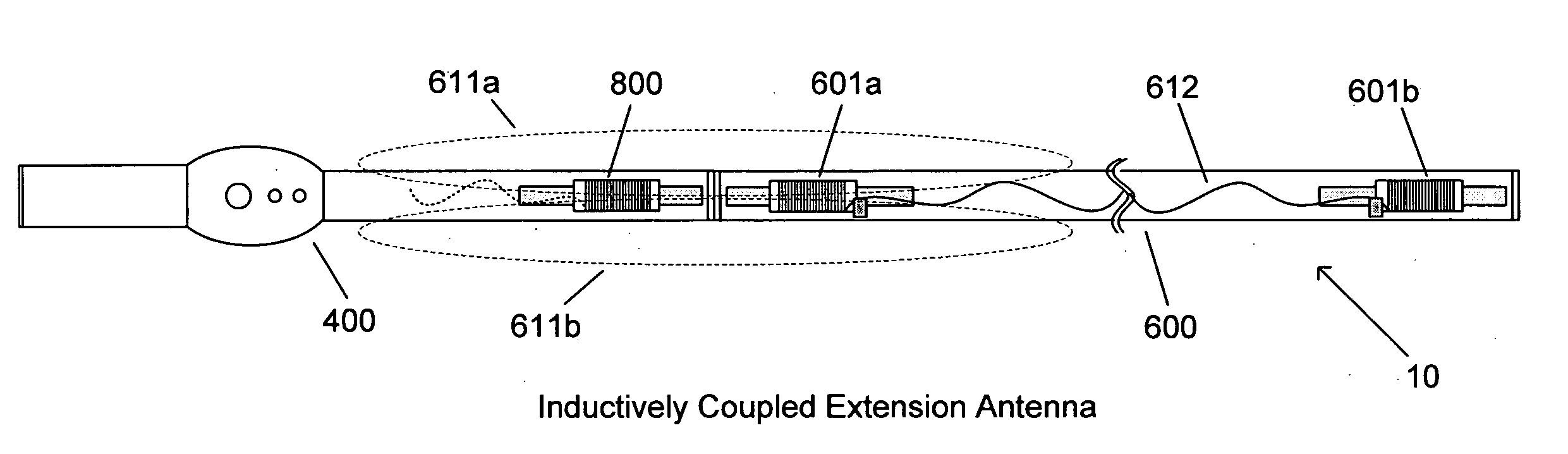
[0052]Turning now to the drawings, portable RFID reader assemblies in accordance with embodiments of the invention are shown that include a portable RFID reader inductively coupled and, in several embodiments physically connected, to an extension antenna. In a number of embodiments, the portable RFID reader is a conventional reader including a resonant antenna and the extension antenna includes a pair of resonant antennas that are electrically connected. In many embodiments, a mechanical joining mechanism attaches the portable RFID reader to the extension antenna and the resonant antenna in the portable RFID reader is inductively coupled to one of the resonant antennas in the extension antenna.
[0053]An embodiment of an RFID reader assembly including an RFID reader inductively coupled to an extension antenna in accordance with an embodiment of the invention is shown in FIG. 6. The composite RFID reader assembly 10 includes a portable RFID reader 400 closely located to an extension an...
PUM
Abstract
Systems and methods are described for adapting a portable RFID reader to create a portable RFID reader assembly that includes an extension antenna. In many embodiments, the extension antenna can be added to increase the reach of the portable RFID reader. The extension antenna is inductively coupled to the portable RFID reader and in many embodiments, the extension antenna is retrofit to an existing portable RFID reader. In other embodiments, a portable RFID reader and one or more extension antennas are produced as part of a set. One embodiment of the invention includes a reader having reader circuitry configured to generate an activation signal, a first antenna, where the first antenna is electrically connected to the reader circuitry, a reader housing containing the reader circuitry, an extension antenna including an elongated housing, a second antenna located at one end of the housing, and a third antenna located at the opposite end of the housing, where the second antenna is electrically connected to the third antenna. In addition, the first antenna and second antenna are inductively coupled.
Description
FIELD OF THE INVENTION[0001]This invention, relates to radio frequency identification (RFID) systems and, more particularly, to an RFID reader that uses a resonant frequency antenna circuit that magnetically couples with electronic identification tags that carry information in the form of digital data.BACKGROUND[0002]Passive low frequency RFID readers and tags use operating principles that are well-know to those of ordinary skill in the art, and that are described in extensive detail in several seminal inventions, including U.S. Pat. No. 1,744,036 to Brard, U.S. Pat. No. 3,299,424 to Vinding, U.S. Pat. No. 3,713,148 to Cardullo et al., and U.S. Pat. No. 5,053,774 to Schuermann et al., and in textbooks such as Finkenzeller, “RFID Handbook” (1st Edition, 1999). The disclosure of U.S. Pat. Nos. 1,744,036, 3,299,424, 3,713,148 and 5,053,774 and the “RFID Handbook” is incorporated herein by reference in its entirety[0003]In RFID systems of this type, the reader (also sometimes referred t...
Claims
Application Information
Patent Timeline
Application Date:The date an application was filed.
Publication Date:The date a patent or application was officially published.
First Publication Date:The earliest publication date of a patent with the same application number.
Issue Date:Publication date of the patent grant document.
PCT Entry Date:The Entry date of PCT National Phase.
Estimated Expiry Date:The statutory expiry date of a patent right according to the Patent Law, and it is the longest term of protection that the patent right can achieve without the termination of the patent right due to other reasons(Term extension factor has been taken into account ).
Invalid Date:Actual expiry date is based on effective date or publication date of legal transaction data of invalid patent.