Magnetic recording device and magnetic recording apparatus

a recording device and magnetic technology, applied in the field of magnetic recording devices and magnetic recording apparatuses, can solve the problems of insufficient magnetic field generation to control the magnetic direction, difficult localization,

Inactive Publication Date: 2009-01-15
KK TOSHIBA
View PDF12 Cites 111 Cited by
  • Summary
  • Abstract
  • Description
  • Claims
  • Application Information

AI Technical Summary

Problems solved by technology

However, a magnetic field intrinsically has the nature of spreading in space, and is difficult to localize.
On the contrary, downsizing the source of magnetic field to localize the magnetic field causes the problem of failing to generate a magnetic field enough to control the magnetization direction.

Method used


Image

  • Magnetic recording device and magnetic recording apparatus
  • Magnetic recording device and magnetic recording apparatus
  • Magnetic recording device and magnetic recording apparatus

Examples


first embodiment

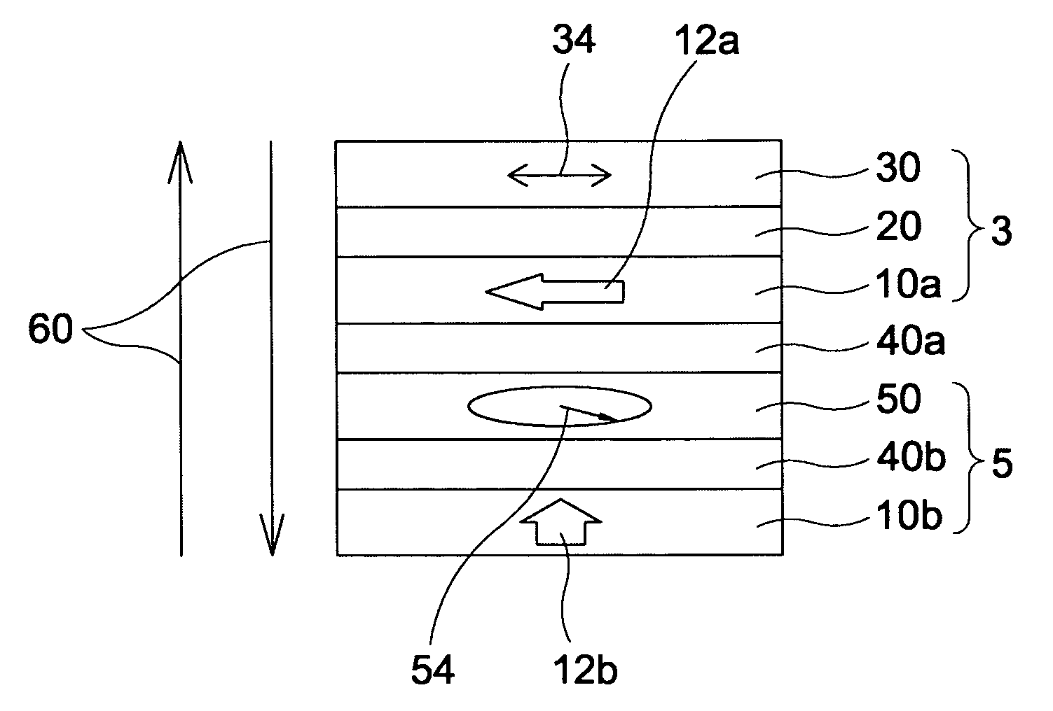
[0036]FIG. 1 is a schematic view illustrating a basic cross-sectional structure of a magnetic recording device according to the invention.

[0037]This magnetic recording device comprises a magnetic recording section 3 and a magnetization oscillator 5. The magnetic recording section 3 and the magnetization oscillator 5 are disposed adjacently across an intermediate layer 40a.

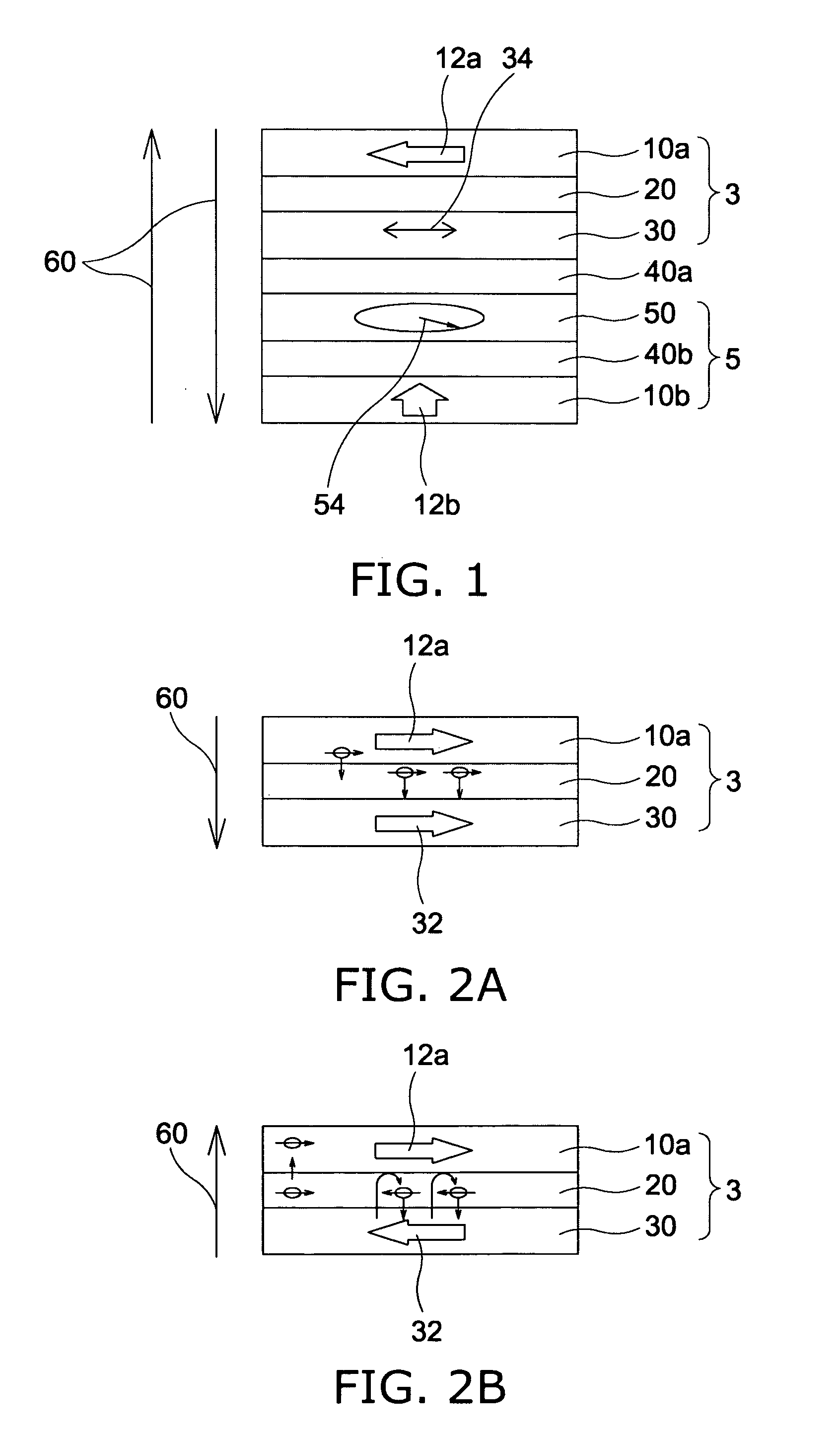
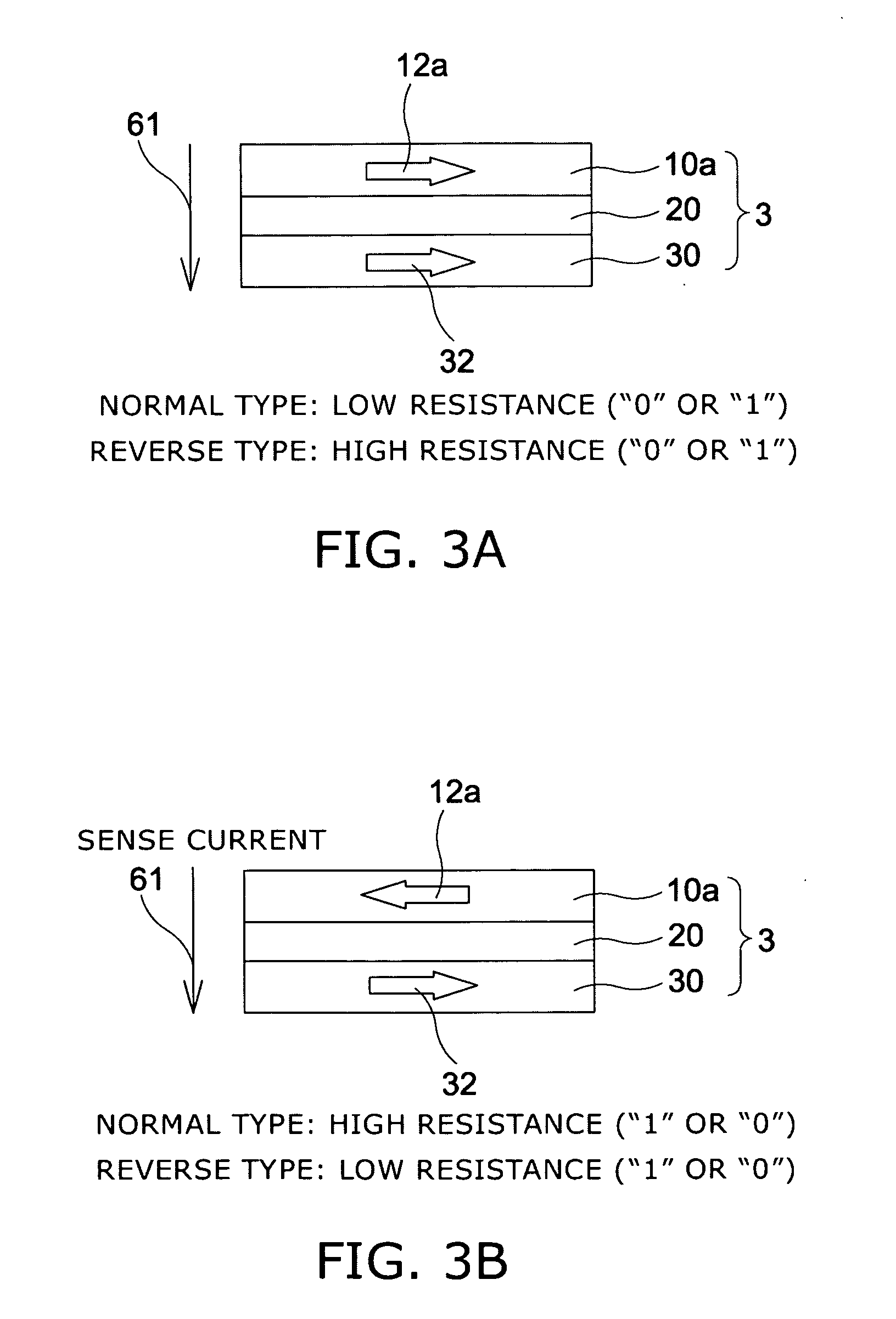
[0038]The magnetic recording section 3 includes a magnetic pinned layer 10a with a magnetization 12a fixed generally parallel to the film plane, a magnetic recording layer 30 with a magnetization easy axis 34 directed generally parallel to the film plane, and a nonmagnetic barrier layer 20 disposed between the magnetic pinned layer 10a and the magnetic recording layer 30. This laminated structure composed of the magnetic pinned layer 10a, the barrier layer 20, and the magnetic recording layer 30 is known as MTJ (magnetic tunnel junction).

[0039]The magnetization oscillator 5 includes a magnetization rotation layer ...

second embodiment

[0151]Next, the invention is described.

[0152]FIG. 13 is a schematic view illustrating a basic cross-sectional structure of a magnetic recording device according to the second embodiment of the invention.

[0153]FIG. 14 is a schematic view illustrating another basic cross-sectional structure of a magnetic recording device according to the second embodiment of the invention.

[0154]The magnetic recording device of this embodiment comprises a magnetic recording section 3, an intermediate layer 40a, and a magnetization rotation layer 50. In the magnetic recording device of FIG. 13, the magnetic recording section 3 includes a magnetic pinned layer 10a with a magnetization 12a fixed generally perpendicular to the film plane, a magnetic recording layer 30 with a magnetization easy axis 34 directed generally perpendicular to the film plane, and a barrier layer 20 disposed between the magnetic pinned layer 10a and the magnetic recording layer 30. In the magnetic recording device of FIG. 14, the ...

third embodiment

[0172]Next, the invention is described.

[0173]FIG. 19 is a plan view illustrating a magnetic recording apparatus according to the third embodiment of the invention.

[0174]The magnetic recording apparatus of this embodiment uses the magnetic recording device of the first embodiment or the magnetic recording device of the second embodiment as a magnetic cell. A switching device (e.g., transistor) is connected in series to the magnetic cell. Each magnetic cell is connected to one addressing row (bit line), and each switching device is connected to one addressing column (word line). The magnetic recording apparatus of this embodiment also includes a power supply for generating a current having a pulse width of 18 nanoseconds or less and 50 picoseconds or more at the time of recording.

[0175]Selection of a magnetic cell is enabled by specifying the word line and the bit line connected to the magnetic cell. More specifically, the bit line is specified to turn on the switching device, thereby...


PUM

PropertyMeasurementUnit
thicknessaaaaaaaaaa
thicknessaaaaaaaaaa
frequencyaaaaaaaaaa

Abstract

A magnetic recording device includes: a laminated body including: a first ferromagnetic layer with a magnetization substantially fixed in a first direction; a second ferromagnetic layer with a variable magnetization direction; a first nonmagnetic layer disposed between the first ferromagnetic layer and the second ferromagnetic layer; and a third ferromagnetic layer with a variable magnetization direction. The magnetization direction of the second ferromagnetic layer is determinable in response to the orientation of a current, by allowing electrons spin-polarized by passing a current in a direction generally perpendicular to the film plane of the layers of the laminated body to act on the second ferromagnetic layer, and by allowing a magnetic field generated by precession of the magnetization of the third ferromagnetic layer to act on the second ferromagnetic layer.

Description

CROSS-REFERENCE TO RELATED APPLICATIONS[0001]This application is based upon and claims the benefit of priority from the prior Japanese Patent Application No. 2007-182286, filed on Jul. 11, 2007; the entire contents of which are incorporated herein by reference.BACKGROUND OF THE INVENTION[0002]1. Field of the Invention[0003]This invention relates to a magnetic recording device and a magnetic recording apparatus in which a radio-frequency magnetic field is applied in combination with a write current.[0004]2. Background Art[0005]Applying a magnetic field is a conventional method for controlling the magnetization direction of a magnetic material. For example, in a hard disk drive (HDD), the magnetization direction of a medium is reversed by a magnetic field generated from a recording head to perform write operation. In a conventional magnetic random access memory, a current is passed through an interconnect disposed near a magnetoresistive effect device to generate a current-induced mag...

Claims


Application Information

Patent Timeline
Patent Type & Authority Applications(United States)
IPC IPC(8): G11B5/02G11B5/62
CPCG11B5/66G11C11/22G11C11/16G11C11/161G11C11/1675
Inventor NAKAMURA, SHIHOMORISE, HIROFUMIYANAGI, SATOSHISAIDA, DAISUKEKIKITSU, AKIRA
Owner KK TOSHIBA
Why Eureka
Try Eureka