Airflow control and dust removal for electronic systems

a technology of electronic systems and airflow control, applied in the direction of cooling/ventilation/heating modification, instruments, computing, etc., can solve the problems of reducing the thermal efficiency of the heatsink, reducing the performance of the system components, and increasing the amount and rate of dust deposited, so as to reduce the airflow to the other processor blades, reduce the airflow, and increase the airflow through the selected processor blades

Inactive Publication Date: 2009-01-15
IBM CORP
View PDF17 Cites 93 Cited by
  • Summary
  • Abstract
  • Description
  • Claims
  • Application Information

AI Technical Summary

Problems solved by technology

Over time, this dust is deposited onto internal components of the computers.
To make matters worse, some of the electronic components in computers and servers tend to generate an electrostatic charge that attracts dust as well, increasing the amount and rate of dust being deposited.
An accumulation of dust in a computer system can cause a variety of problems, including a reduction in the performance of system components.
For example, dust deposited on heatsink fins can reduce the thermal efficiency of the heatsink.
Dust can also reduce component life by interfering with operation of moving parts, such as fan blades and mechanical connectors.
Dust can reduce the reliability of electrical components by depositing dust particles between electrical contacts in electrical connectors.
Dust can even give off a foul odor in the presence of hot components.
However, air filtration and other common precautions are not completely effective against all sources of dust.
Over time, there is a likelihood that dust will accumulate on the internal components of the computers.
However, dust removal is significantly more challenging in larger computer systems, such as multi-server rack systems in data centers, where tens or even hundreds of individual blade servers may be present, along with other system hardware.
Thus, removing dust from larger computer systems can be particularly time consuming and costly.

Method used


Image

  • Airflow control and dust removal for electronic systems
  • Airflow control and dust removal for electronic systems
  • Airflow control and dust removal for electronic systems

Examples


Embodiment Construction

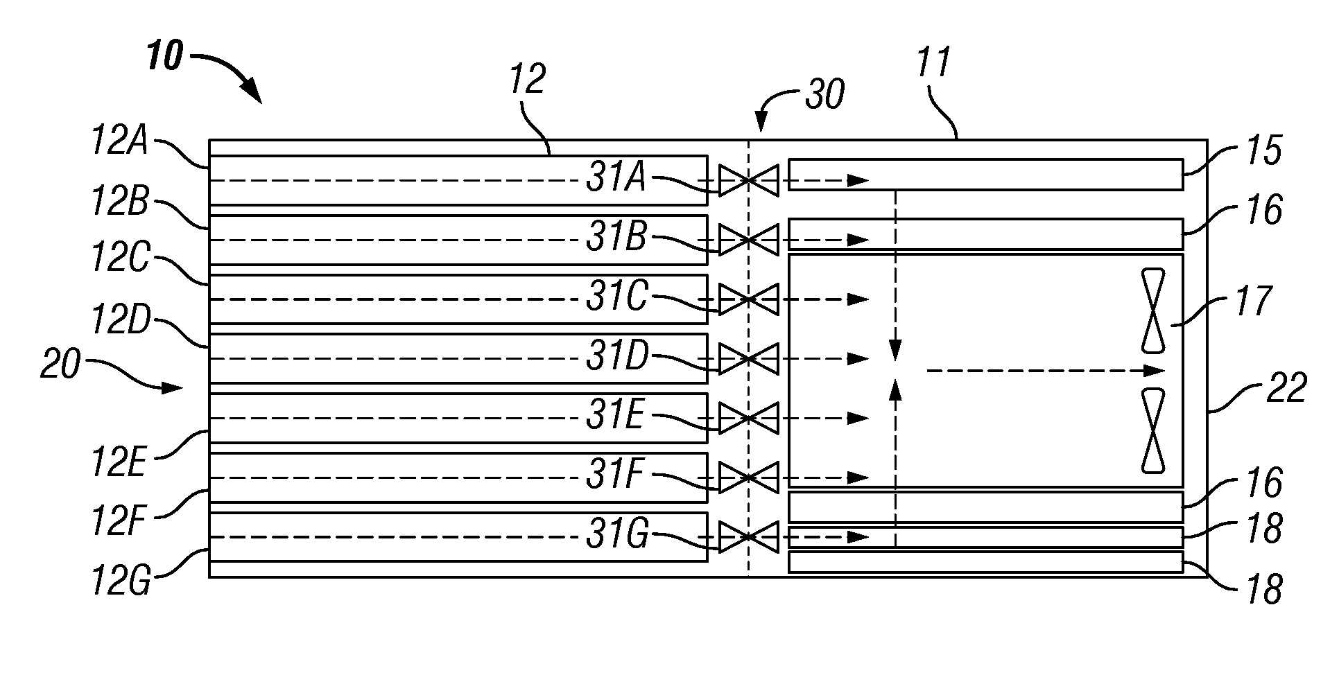
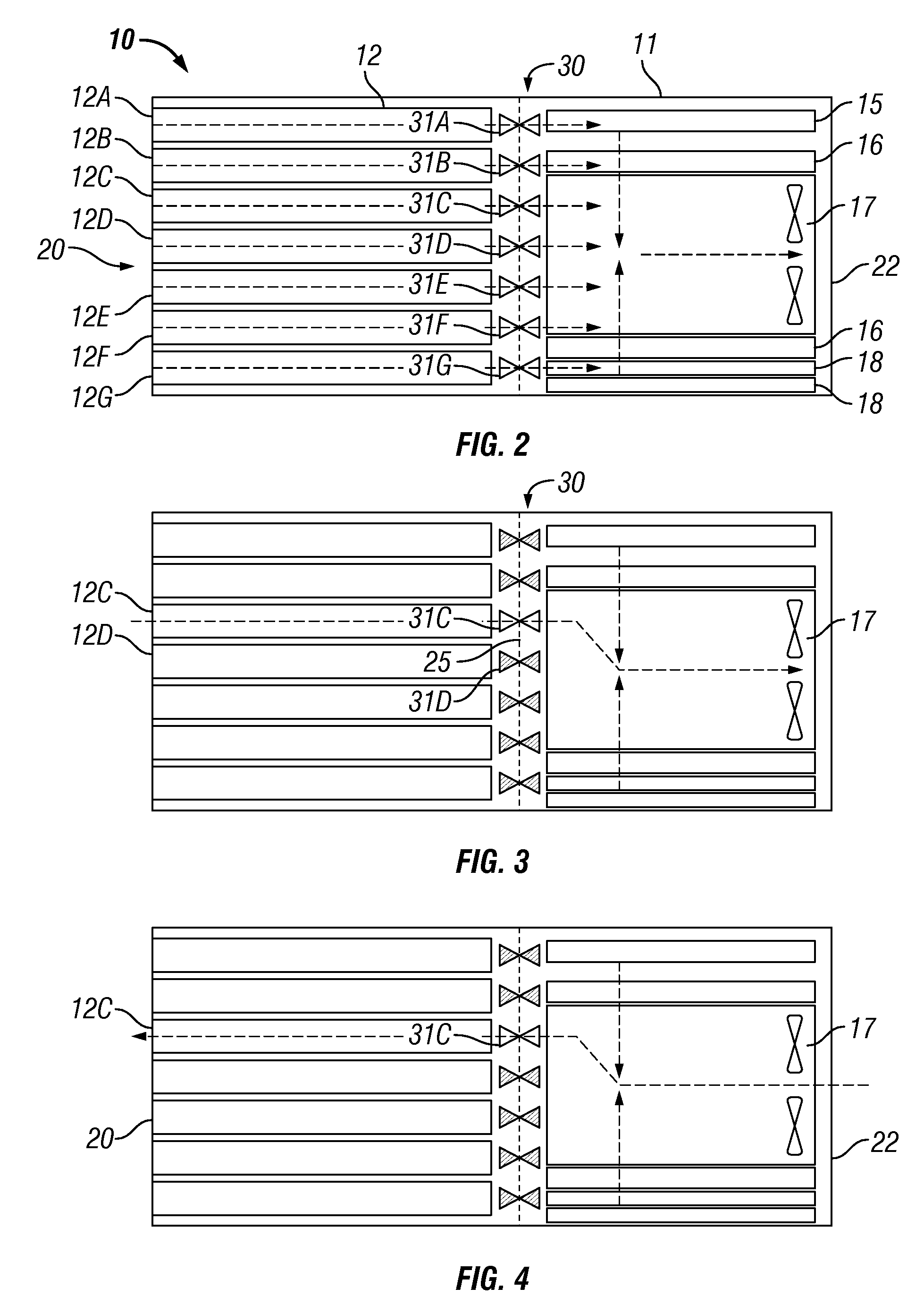
[0027]The present invention provides systems and methods for controlling airflow in electronic systems to selectively remove dust from hardware devices such as servers. An electronic system is normally operated with air flow being directed through a plurality of hardware devices in parallel, i.e., air flows through the devices substantially simultaneously rather than consecutively. This parallel air flow removes heat generated by the hardware devices to cool the hardware devices. The present invention provides both a “cooling mode,” wherein the airflow is directed through a plurality of hardware devices in parallel, and a “cleaning mode,” in which airflow is closed or at least reduced to one or more of the hardware devices in order to increase the airflow rate through one or more other hardware devices. This increased airflow provided during the cleaning mode removes dust from the hardware devices through which it flows.

[0028]The airflow rate through a hardware device selected to be...


PUM


Abstract

Airflow control and dust removal systems and methods are disclosed. In one embodiment, a plurality of blade servers is mounted in a chassis. A blower generates airflow through the chassis. Air enters the chassis uniformly across the blade servers and flows in parallel through the servers. An airflow directing mechanism is provided for allowing airflow through a selected one of the blade servers while reducing or closing airflow to the other blade servers, to individually clean and remove dust from the selected blade server. The airflow directing mechanism may include a movable vane actuated by a rotary or linear solenoid to selectively block airflow ports of the servers. The vane may be held in a closed position, assisted by an electromagnet. The airflow directing mechanism may alternatively comprise a rolled shade having a pattern of openings. The position of the rolled shade may be controlled to align openings in the shade with airflow ports in the servers, to control which servers airflow may pass through.

Description

BACKGROUND OF THE INVENTION[0001]1. Field of the Invention[0002]The present invention relates to controlling airflow through a computer system and to removing dust from hardware devices included within the computer system.[0003]1. Description of the Related Art[0004]Blowers or fans are used to generate airflow through a computer to cool its components. For example, in an individual personal computer (PC), one or more on-board cooling fans are enclosed within the PC housing that contains the motherboard, power supply, memory, and other internal components. The on-board cooling fan drives airflow through the housing to cool the internal components and exhausts the heated air through the back of the PC. In larger computer systems, such as rack-based computer systems having multiple server blades, one or more external blower modules are supported on a chassis along with the servers to generate airflow through the servers and other components.[0005]The airflow used to cool a computer als...

Claims


Application Information

Patent Timeline
Patent Type & Authority Applications(United States)
IPC IPC(8): H05K7/20
CPCH05K7/20736G06F1/20
Inventor BANDHOLZ, JUSTIN POTOKDURHAM, ZACHARY BENSONKERR, CLIFTON EHRICHMAXWELL, JOSEPH ERICREINBERG, KEVIN MICHAELVERNON, KEVIN S.WEINSTEIN, PHILIP LOUISWEST, CHRISTOPHER COLLIER
Owner IBM CORP
Why Eureka
Try Eureka