X-ray apparatus, image processing display apparatus and computer program product

a technology of image processing and display apparatus, applied in the field of x-ray equipment, can solve the problems of difficulty in moving the guide wire ahead in the blood vessel, operator's inability to grasp whether the blood vessel lesion-site is present in front or back, and sometimes decreased accuracy of operation

Active Publication Date: 2009-01-15
TOSHIBA MEDICAL SYST CORP
View PDF1 Cites 128 Cited by
  • Summary
  • Abstract
  • Description
  • Claims
  • Application Information

AI Technical Summary

Problems solved by technology

Under the PCI treatment, it is difficult to grasp a lumen form in a coronary-artery coarctation area only by referring to an X-ray image as a guide image, consequently, accuracy of operation may be sometimes decreased in some cases.
However, it is sometimes difficult to move the guide wire ahead in a blood vessel during a PCI treatment in some cases even by using the coronary-artery analysis software.
However, for example, if the coronary artery is imaged from the direction of an arrow shown in the upper section of the figure, an operator cannot grasp whether the blood-vessel lesion-site is present in front or in the back.
In such case, the operator cannot determine to which direction the guide wire is to be turned, and cannot move the guide wire ahead inside the blood vessel.
H

Method used


Image

  • X-ray apparatus, image processing display apparatus and computer program product
  • X-ray apparatus, image processing display apparatus and computer program product
  • X-ray apparatus, image processing display apparatus and computer program product

Examples


first embodiment

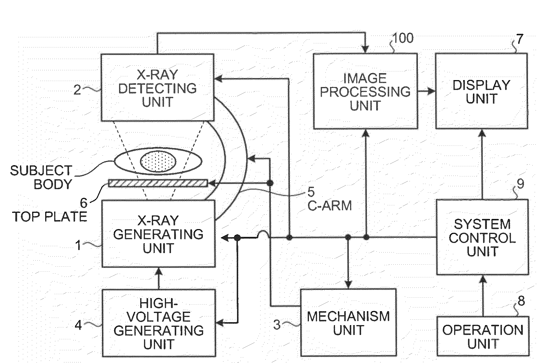
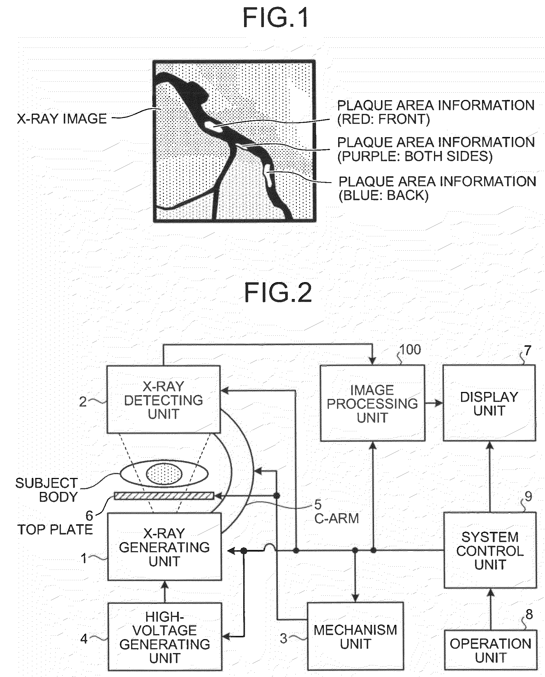
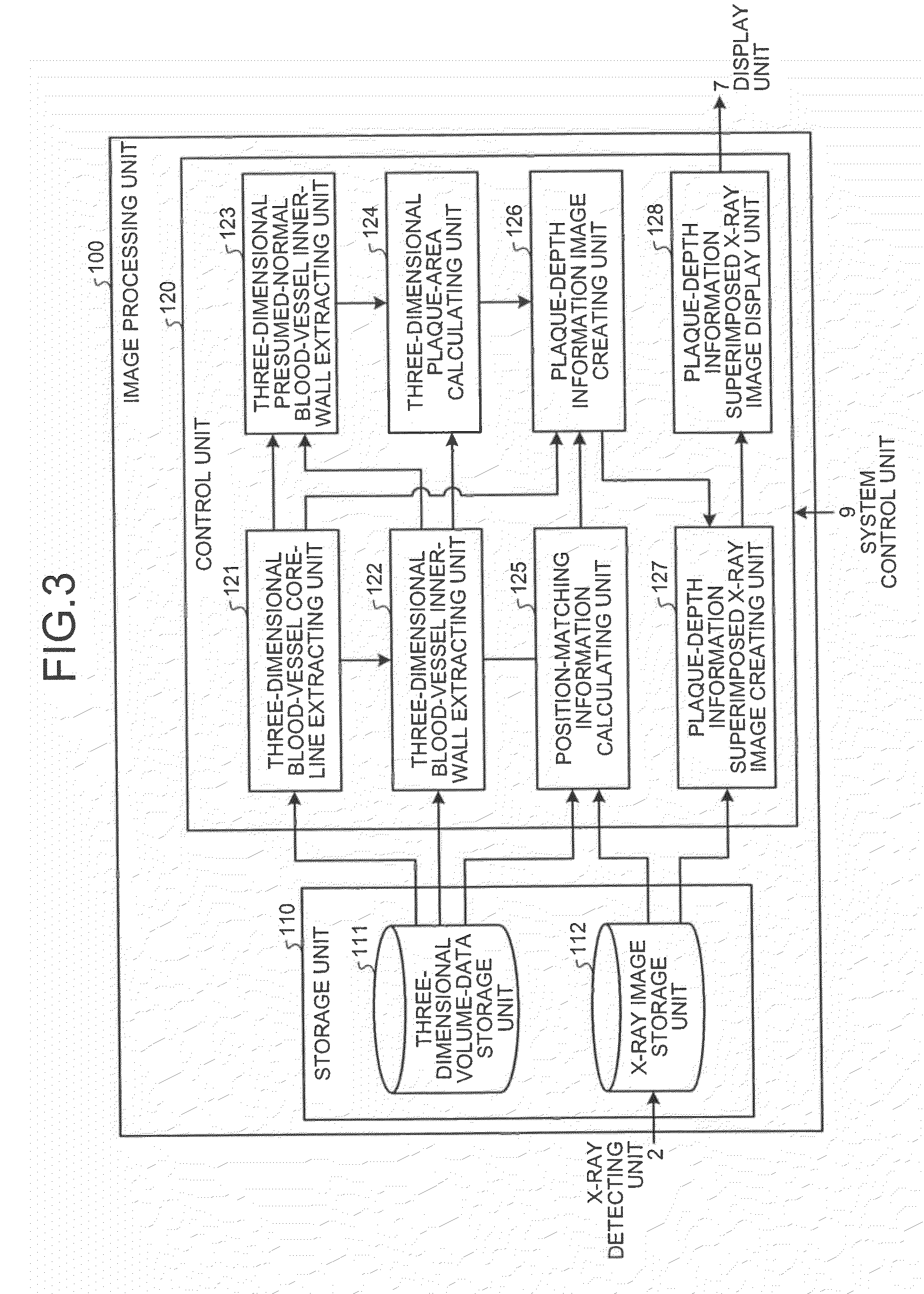
[0057]The image processing unit 100 is a processing unit that creates an X-ray image based on X-ray image data created by the X-ray detecting unit 2. FIG. 3 is a functional block diagram of a configuration of the image processing unit 100 according to the As shown in the figure, the image processing unit 100 includes a storage unit 110 and a control unit 120.

[0058]The storage unit 110 stores therein data and a program required for the control unit 120 to perform various processing, and includes a three-dimensional volume-data storage unit 111 and an X-ray image storage unit 112, which are relevant to the present invention.

[0059]The three-dimensional volume-data storage unit 111 stores therein three-dimensional volume data of an image of a heart area imaged by performing coronary imaging with an X-ray CT apparatus. It is assumed that the three-dimensional volume-data storage unit 111 stores therein, prior to a PCI treatment, three-dimensional volume data of an image imaged in advanc...

second embodiment

[0106]FIG. 9 is a functional block diagram of a configuration of an image processing unit 200 according to the As shown in the figure, the image processing unit 200 includes the storage unit 110 and a control unit 220.

[0107]The control unit 220 controls processing of X-ray image data received from the X-ray detecting unit 2, under the control of the system control unit 9. As units relevant to the present invention, the control unit 220 includes, the three-dimensional blood-vessel core-line extracting unit 121, the three-dimensional blood-vessel inner-wall extracting unit 122, the three-dimensional presumed normal-blood-vessel inner-wall extracting unit 123, the three-dimensional plaque-area calculating unit 124, a position-matching information calculating and MIP-image creating unit 225, the plaque-depth information image creating unit 126, and a plaque-depth information superimposed MIP-image creating unit 227a, a plaque-depth information superimposed MIP-image attached X-ray imag...

third embodiment

[0125]FIG. 11 is a schematic diagram for explaining a concept of displaying blood-vessel running-direction information performed by the X-ray angiographic apparatus according to the As shown in the figure, for example, the X-ray angiographic apparatus creates a blood-vessel running-direction information image in which the color of a blood vessel is varied in accordance with whether the blood vessel is shallow or deep in the projection direction. The X-ray angiographic apparatus then displays the created blood-vessel running-direction information image over an X-ray image in a superimposed manner, as shown in the figure.

[0126]Thus, because the X-ray angiographic apparatus according to the third embodiment displays an image of a blood vessel of which color is varied in accordance with whether the blood vessel is shallow or deep in the projection direction, an operator can easily grasp a blood-vessel running direction. In other words, the X-ray angiographic apparatus according to the ...


PUM


Abstract

An X-ray imaging machine is configured such that a three-dimensional blood-vessel information creating unit creates information concerning a three-dimensional blood-vessel core line and a position of a plaque in a subject blood vessel based on three-dimensional volume data obtained from an image taken by an X-ray computed tomography apparatus. A plaque-depth information image creating unit creates a plaque-depth information image on which the plaque is differently displayed in accordance with whether the plaque is present in front of or in the back of the three-dimensional blood-vessel core line with respect to a projection direction, based on the created information concerning the three-dimensional blood-vessel core line and the position of the plaque. An X-ray image display unit displays the created plaque-depth information image over an X-ray image in a superimposed manner.

Description

CROSS-REFERENCE TO RELATED APPLICATIONS[0001]This application is based upon and claims the benefit of priority from the prior Japanese Patent Application No. 2007-180761, filed on Jul. 10, 2007, and No. 2008-121516, filed on May 7, 2008; the entire contents of which are incorporated herein by reference.BACKGROUND OF THE INVENTION[0002]1. Field of the Invention[0003]The present invention relates to an X-ray apparatus, such as an X-ray angiographic apparatus, an image processing display apparatus, and a computer program product, and particularly relates to a technology for assisting a treatment that is performed by inserting a linear structure, such as a guide wire, into a blood vessel.[0004]2. Description of the Related Art[0005]Conventionally, there has been a treatment method for expanding a narrowed portion or a blocked portion of a coronary artery by inserting a linear structure, such as a guide wire or a catheter, into a coronary artery of a heart. Such treatment is called as Pe...

Claims


Application Information

Patent Timeline
IPC IPC(8): A61B6/00
CPCA61B5/02007A61B6/032A61B6/504A61B6/466A61B6/12
Inventor KAWASAKI, TOMOHIROYAMAGATA, HITOSHI
Owner TOSHIBA MEDICAL SYST CORP
Why Eureka
Try Eureka