Landscape retaining stake

a technology for retaining stakes and landscapes, applied in the field of stakes, can solve the problems of affecting the smooth and attractive surface originally intended, affecting the appearance, and affecting the appearance, so as to achieve the effect of preventing sinking and reducing the damage to the ston

Inactive Publication Date: 2009-01-15
KEYSTONE RETAINING WALL SYST
View PDF32 Cites 7 Cited by
  • Summary
  • Abstract
  • Description
  • Claims
  • Application Information

AI Technical Summary

Benefits of technology

[0007]The front face of the body is adapted for sliding contact with the stone and forms a fulcrum about which the body is adapted to pivot. The rear face is inclined rearwardly from bottom to top to form a wedge. As the stake is driven into the ground the wedge urges the stake laterally towards the stone reducing a common problem of stakes migrating away from the stone while being driven. The wedge also causes the body of the stake to pivot about the lower edge of the stone so that the lower end of the body moves in under the stone as the stake is driven into the ground.
[0008]The head includes an anvil, impact or striking surface that is generally perpendicular to the front face of the body, and an abutment projecting forwardly from the anvil surface beyond the front face of the body. The anvil surface is preferably located so that impact or blows imparted to the same define a line of applied force extending longitudinally of the body and preferably offset rearwardly from the center line of the body. This eccentric loading contributes in causing the body to pivot or turn under the stone as the body is driven into the ground. The abutment has a forwardly facing stone restraining abutment surface that is brought into engagement with the side of the stone when the body is driven fully into the ground. The front face of the body at or near the juncture of the abutment surface is adapted to engage the base edge of the stone. The abutment surface and front face engage and support the stone both horizontally, to prevent lateral movement, and vertically, to prevent sinking. Additionally, the abutment spaces the anvil or striking surface laterally away from the stone, thereby mitigating damage to the stone from inadvertent hammer blows.

Problems solved by technology

Consequently, there is a tendency for the stones to migrate laterally, to shift and sink, and to fall into disarray, leaving an unsightly and potentially dangerous walking surface rather than the smooth and attractive surface originally intended.
Similarly, stones are employed for flowerbed and lawn borders and edgings and the like have a tendency to shift and fall into disarray.
Stakes have a tendency to migrate away from the edge of the stone(s) and thereby fail to provide lateral support.
However, edging strips cannot be used when the border is irregular, as is the case with natural (or artificial) stone patios, walkways, etcetera.
Many retaining systems are designed to provide lateral retention, but fail to provide vertical retention to prevent the marginal edges from “sinking.”
Prior art landscape retaining systems thus have met with varying degrees of success and failure.

Method used


Image

  • Landscape retaining stake
  • Landscape retaining stake
  • Landscape retaining stake

Examples


Embodiment Construction

[0013]The following is a description of an embodiment of the invention presently contemplated by the inventors to be the best mode of carrying out their invention.

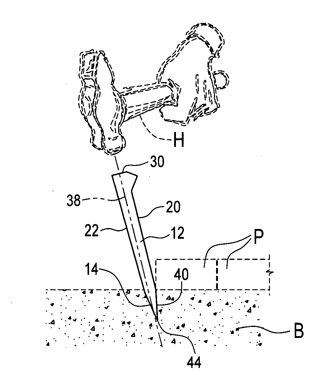
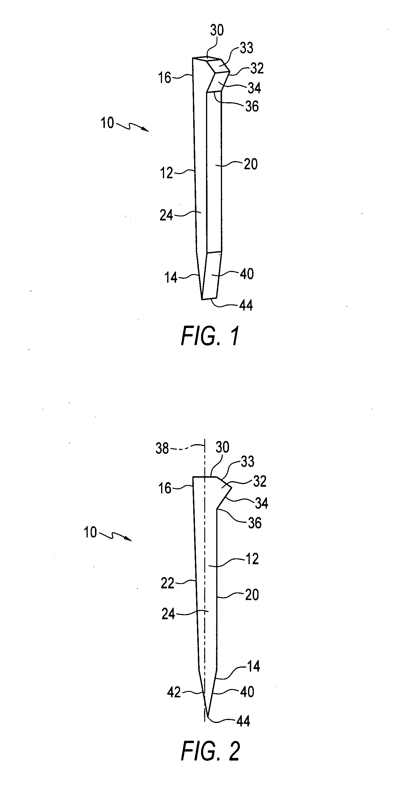
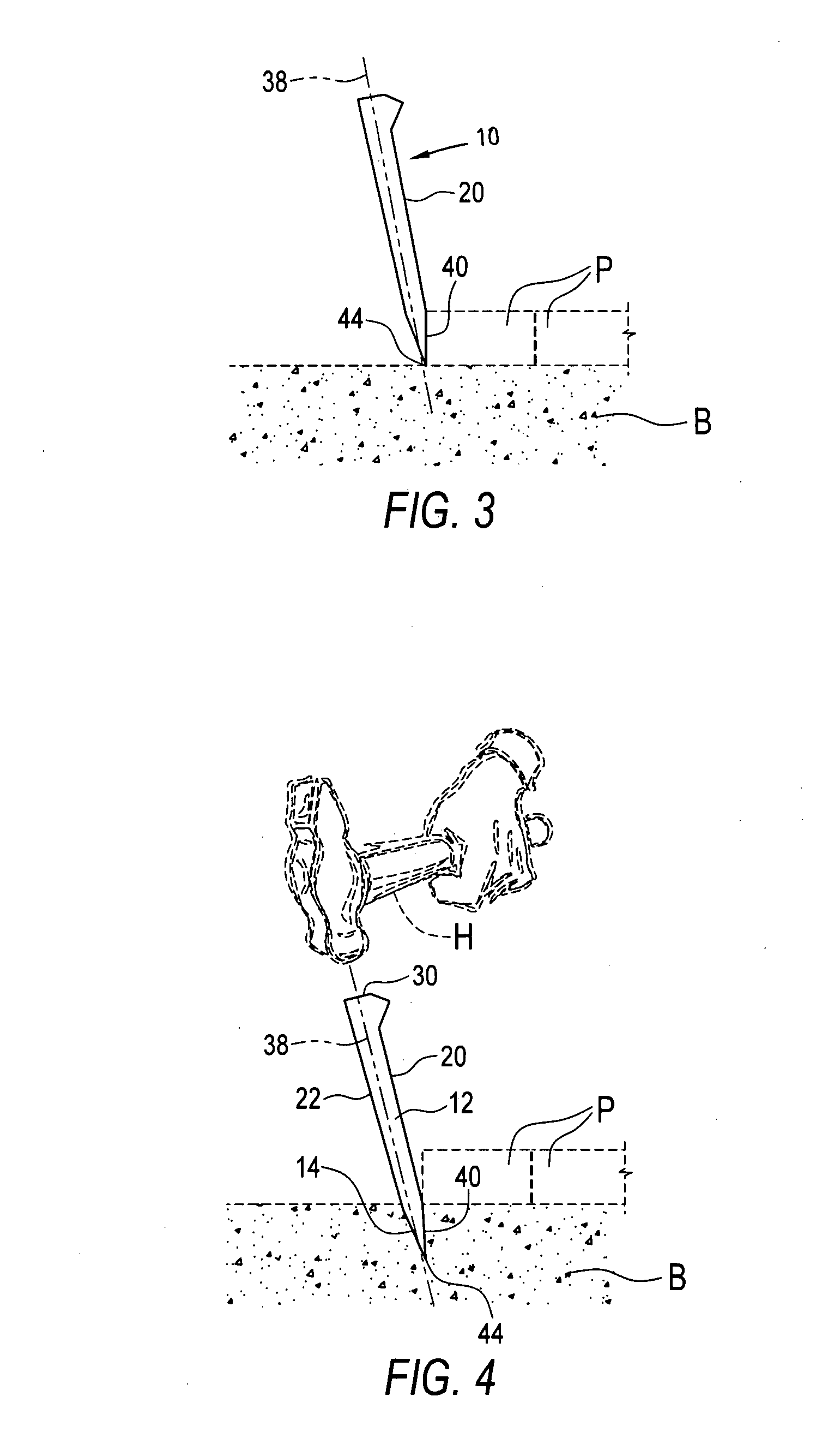
[0014]Referring to the drawings, particularly FIGS. 1 and 2, the landscape retaining stake of the invention, indicated generally at 10, is comprised of an elongate body 12 having a tapered lower end 14 and an upper end or head 16. The cross-sectional shape of body 12 is shown as being essentially square, but could be other shapes such as H-shape. The lower tapered end is preferably chisel-shaped. The stake may be made of any rigid, sturdy and long lasting material, such as metal, plastic and preservative treated wood.

[0015]The length and cross-section of the body 12 may be sized according to the demands of the particular application for which the stake is intended. For conventional garden, footpath and patio applications, a recommended cross-section is in the order of ¾ inch by ¾ inch and a recommended length is about 8 to...


PUM


Abstract

A stake for securing stones, pavers, bricks and other landscape units comprises an elongate body having an upper end including an anvil surface and an abutment, a chisel shaped lower end, a front face, and a rear face that is inclined rearwardly relative to the front face of the body from the lower end of the body to the upper end of the body to form a wedge. When the stake is aligned with a stone and is driven into the ground, it pivots underneath the stone, and the abutment engages a lower edge of the stone to restrain shifting of the stone laterally and sinking of the stone vertically.

Description

FIELD OF THE INVENTION[0001]The present invention relates to devices, particularly stakes, for retaining in place pavers, bricks and landscape stones employed in outdoor patios, walkways, flowerbed borders and other landscape settings.BACKGROUND[0002]Outdoor patios, driveways and walkways are frequently formed by placing landscape stones on a bed of sand or gravel. Typically, no cementitious or other binding material is employed to lock the stones in place. Consequently, there is a tendency for the stones to migrate laterally, to shift and sink, and to fall into disarray, leaving an unsightly and potentially dangerous walking surface rather than the smooth and attractive surface originally intended. Similarly, stones are employed for flowerbed and lawn borders and edgings and the like have a tendency to shift and fall into disarray.[0003]Many systems have been proposed for retaining the marginal edge elements of such patios, walkways and edgings in place, thereby to constrain all of...

Claims


Application Information

Patent Timeline
Patent Type & Authority Applications(United States)
IPC IPC(8): F16B15/00E02D27/01
CPCA01G1/08F16B15/00E01C11/221A01G9/28Y02A30/60
Inventor RICCOBENE, THOMAS S.NYGHT, MERLYN D.
Owner KEYSTONE RETAINING WALL SYST
Why Eureka
Try Eureka