Wireless communication system
a communication system and wireless technology, applied in the field of wireless communication systems, can solve the problems of dividing a leaky transmission line, power loss of 6 db, and attempting to increase the wireless area that is not expected, so as to avoid division losses, increase the effective length of leaky transmission lines, and avoid losses
- Summary
- Abstract
- Description
- Claims
- Application Information
AI Technical Summary
Benefits of technology
Problems solved by technology
Method used
Image

Examples
first embodiment
(A) First Embodiment
[0023]A wireless communication system according to a first embodiment of the present invention is described in detail below with reference to the figures.
(A-1) Configuration of the First Embodiment
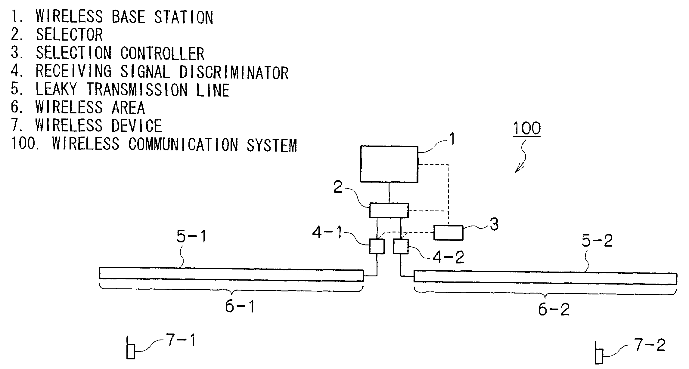
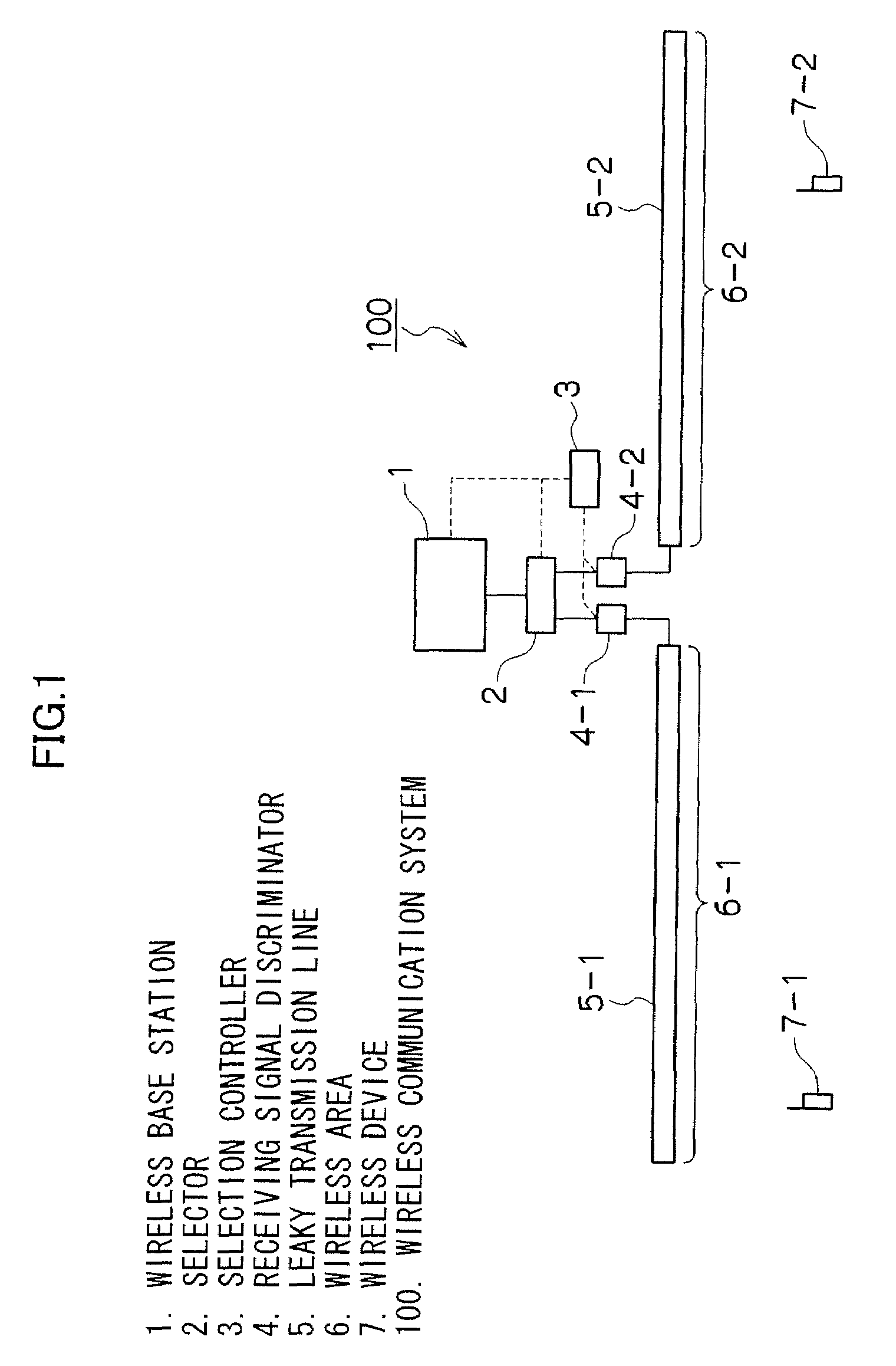
[0024]FIG. 1 is a block diagram illustrating a wireless communication system 100 according to the first embodiment. The wireless communication system 100 of FIG. 1 includes a wireless base station 1, a selector 2, a selection controller 3, receiving signal discriminators 4-1 and 4-2, leaky transmission lines 5-1 and 5-2, and wireless devices 7 (7-1 and 7-2).
[0025]The wireless base station 1, for example, may be inside a base control station (not illustrated) and under the control thereof, thereby connecting to an external network (such as a public Internet Protocol (IP) network). The wireless base station 1 enables communications of the wireless devices 7 (7-1 and 7-2) with the external network, as well as communications of the wireless devices 7 with each other. Antenn...
second embodiment
(B) Second Embodiment
[0064]Herewith, a wireless communication system according to a second embodiment of the present invention is described with reference to the figures.
(B-1) Configuration of the Second Embodiment
[0065]FIG. 7 is a block diagram illustrating a wireless communication system 200 according to the second embodiment. The same numerals are used for elements corresponding to those according to the first embodiment in FIG. 1. FIG. 7 illustrates an example of four leaky transmission lines functioning as antennas of one wireless base station.
[0066]The wireless communication system 200 of FIG. 7 includes a wireless base station 1, a selector 2, a selection controller 3, an receiving signal discriminator 4, leaky transmission lines 5-1 through 5-4, and wireless devices 7 (7-1 and 7-2).
[0067]The wireless communication system 200 according to the second embodiment is similar to that of the first embodiment, except for the number of the leaky transmission lines 5-1 through 5-4, an...
third embodiment
(C) Third Embodiment
[0083]Herewith, a wireless communication system according to a third embodiment of the present invention is described with reference to the figures.
[0084]FIG. 11 is a block diagram illustrating the wireless communication system 300 according to the third embodiment. The same numerals are used for elements corresponding to those of the first embodiment in FIG. 1 and the second embodiment in FIG. 7. FIG. 11 illustrates an example including four leaky transmission lines functioning as antennas of one wireless base station 1.
[0085]The wireless communication system 300 of FIG. 11 includes a wireless base station 1, a selector 2, leaky transmission lines 5-1 through 5-4, and wireless devices 7 (7-1 and 7-2). In other words, the third embodiment does not include the selection controller 3 and the receiving signal discriminator 4.
[0086]The selector 2 according to the third embodiment sequentially selects each of the leaky transmission lines 5-1 through 5-4, selecting onl...
PUM
 Abstract
Description
Claims
Application Information
 - R&D
- Intellectual Property
- Life Sciences
- Materials
- Tech Scout
- Unparalleled Data Quality
- Higher Quality Content
- 60% Fewer Hallucinations
Browse by: Latest US Patents, China's latest patents, Technical Efficacy Thesaurus, Application Domain, Technology Topic, Popular Technical Reports.
© 2025 PatSnap. All rights reserved.Legal|Privacy policy|Modern Slavery Act Transparency Statement|Sitemap|About US| Contact US: help@patsnap.com