Flexible electric load management system and method therefore

a load management system and flexible technology, applied in the integration of power network operation systems, process and machine control, instruments, etc., can solve the problems of not knowing if a power reduction will be realized, many electric utilities around the world suffer from lack of electricity, and customers are often paid

Inactive Publication Date: 2009-01-15
COMPUTERIZED ELECTRICITY SYST LTD
View PDF6 Cites 104 Cited by
  • Summary
  • Abstract
  • Description
  • Claims
  • Application Information

AI Technical Summary

Benefits of technology

[0022]According to still further features in the described preferred embodiments, the main central processing unit is configured to command each relay to close and open so that a total power consumption consumed by the plurality of loads is held beneath a power consumption threshold.
[0023]According to still further features in the described preferred embodiments, the main central processing unit controls an order of opening and closing of the relays based on rules preprogrammed into the main central processing unit, the rules including: (I) the main central processing unit closes at least a first relay, so as to cut off power to at least one of the loads, according to a lowest priority of the consumer.
[0024]According to still further features in the described preferred embodiments, prior to (I) the main central processing unit determines, based on historical data on current drawn through the first relay, that the cut off of the power will reduce the total power consumption below the power consumption threshold.

Problems solved by technology

It is known that many electric utilities around the world suffer from lack of electricity at peak demand hours.
But in the middle of a heat wave, the consumer may find himself with an air-conditioning unit that he wishes to operate, but cannot.
Another disadvantage of such systems is that customers are often paid for participating in such a program, whether or not the utility actually implements the cutoff.
Another ramification of this load-shedding approach is that the utility, in transmitting a command to cut off power to an appliance, does not know if a power reduction will indeed be realized.
However, such systems are highly involved, costly and correspondingly inconvenient to install and maintain.
The systems may include a large plurality of microprocessors, according to the number of loads being controlled, and the resulting inter-microprocessor communication is complicated.
In addition, each node is installed separately, resulting in the system being sprawled around the premises of the consumer.
A node may be installed within the load, but tampering with the electronics in the load is involved and may invalidate warrantees on the load.
A node not contained within the load itself, is exposed to possible unintentional damage and to the environment.
Furthermore, in an already constructed residential building, such nodes tend to be visible, creating an eyesore that the consumer would have reason to conceal.
As a result of the cost and inconvenience, such systems appear to be largely impractical.

Method used


Image

  • Flexible electric load management system and method therefore
  • Flexible electric load management system and method therefore
  • Flexible electric load management system and method therefore

Examples


Embodiment Construction

[0035]One aspect of the present invention is a flexible, centralized electric load management system. The principles and operation of this flexible, centralized electric load management system according to the present invention may be better understood with reference to the drawings and the accompanying description.

[0036]Before explaining at least one embodiment of the invention in detail, it is to be understood that the invention is not limited in its application to the details of construction and the arrangement of the components set forth in the following description or illustrated in the drawings. The invention is capable of other embodiments or of being practiced or carried out in various ways. Also, it is to be understood that the phraseology and terminology employed herein is for the purpose of description and should not be regarded as limiting.

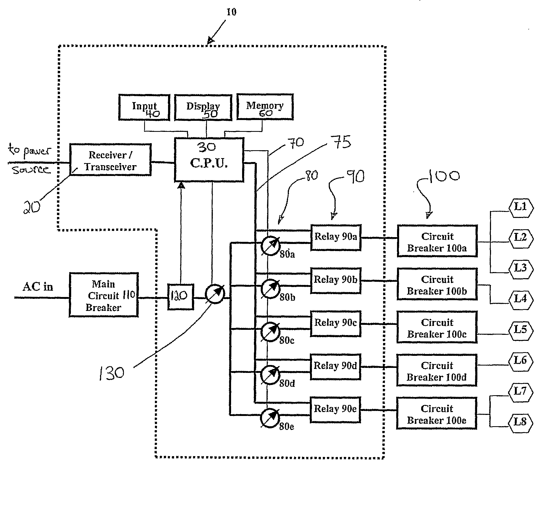
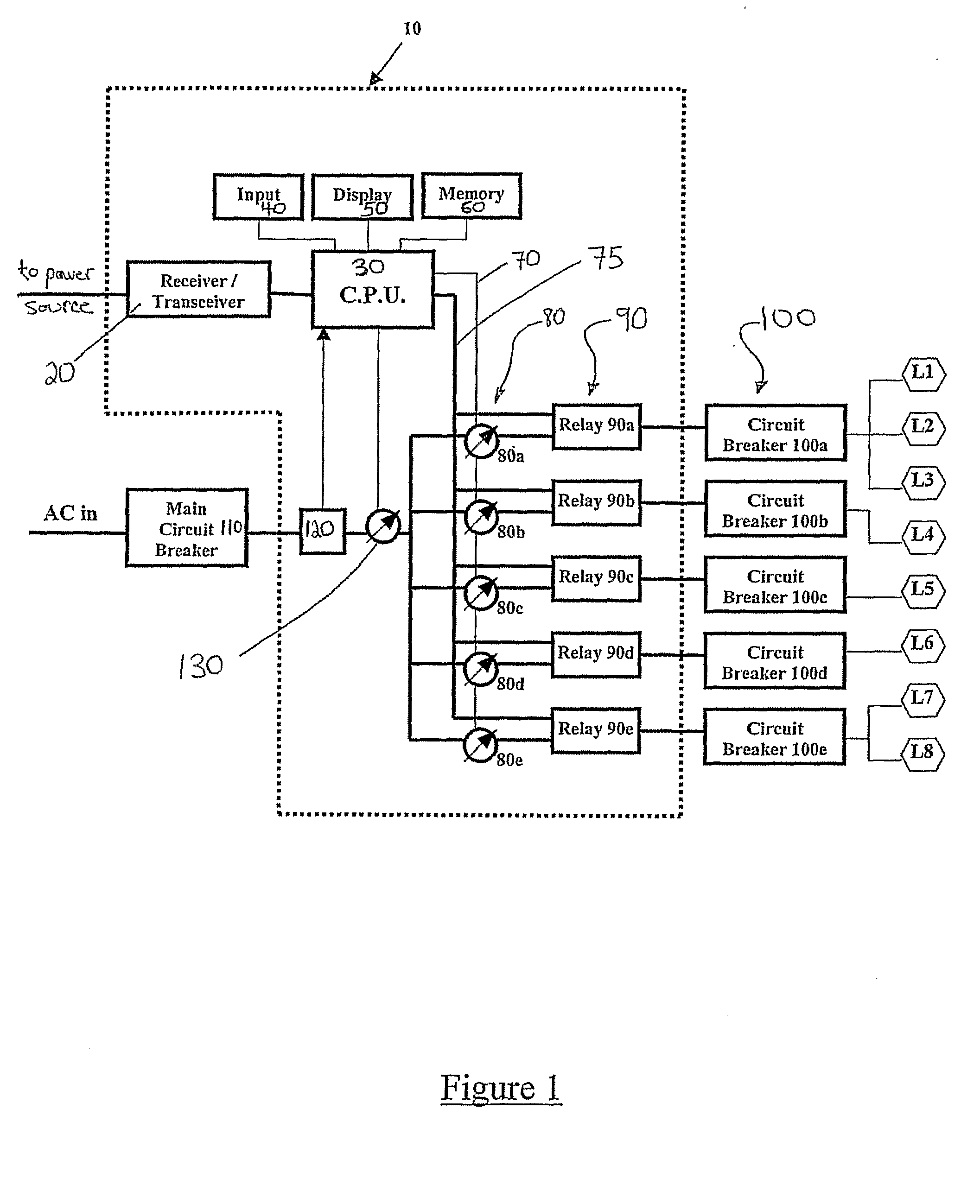
[0037]Referring now to the drawings, FIG. 1 is a block diagram of a preferred embodiment of a flexible electric load management syste...


PUM


Abstract

A system for controlling electricity consumption of an electricity consumer having a plurality of loads, including: (a) a main central processing unit, connected to a power source, and adapted to receive a signal therefrom; (b) a memory associated with the processing unit; (c) controlled relay assemblies connected to a plurality of loads via local circuit breakers, each assembly including: (i) a relay, responsive to the processing unit; (ii) a current sensor, electrically connected to the relay, the relay and the current sensor being electrically associated with the processing unit, and (iii) an electrical line having a first end connecting the relay assembly to the power source, and having a second end connecting to a local circuit breaker connected to at least one load; wherein each current sensor is adapted to provide, to the processing unit, data pertaining to current drawn via a particular local circuit breaker, and wherein the processing unit is configured to command the relay based on the signal received from the power source, and based on a set of rules provided to the processing unit, the set of rules including load priority information, such that each relay opens or closes in response to the command from the processing unit, so as to shut off or restore power to the electrical line.

Description

FIELD AND BACKGROUND OF THE INVENTION[0001]The present invention relates to a computerized system for monitoring and controlling electricity consumption, and, more particularly, to a flexible system and method for electric power management.[0002]It is known that many electric utilities around the world suffer from lack of electricity at peak demand hours. Historically, demand for power increases each year, especially during peak heating and cooling months, resulting in a need for ever-increasing amounts of generation capacity. The deregulation of the electric industry has heightened concerns over power outages, price volatility and how the eventual outcome will impact the economy and our way of life. Demand reduction programs and more advanced controls have been proposed to assist in reducing demand during peak times.[0003]Electric utilities have been expanding demand-side management (DSM) programs to promote energy efficiency, reduce toxic air emissions, and achieve cost effectiven...

Claims


Application Information

Patent Timeline
Patent Type & Authority Applications(United States)
IPC IPC(8): G06F1/32G06F1/26G06N5/02
CPCH02J3/14Y04S20/222Y02B70/3225H02J2310/60
Inventor WITTNER, LUPU
Owner COMPUTERIZED ELECTRICITY SYST LTD
Why Eureka
Try Eureka