System and method for a pumping torque estimation model for all air induction configurations

a technology of estimation model and air induction configuration, which is applied in the field of system and method of pumping torque estimation model, can solve the problems of insufficient conventional pumping torque model and the inability to use the model for air induction configurations other than the one used

Inactive Publication Date: 2009-01-15
DELPHI TECH INC
View PDF4 Cites 16 Cited by
  • Summary
  • Abstract
  • Description
  • Claims
  • Application Information

AI Technical Summary

Benefits of technology

[0006]The present invention is directed to a system and method for determining a pumping torque for an internal combustion engine that has a pumping torque (loss) estimation model that will work with any one of a number of air induction configurations (e.g., naturally-aspirated (NA), turbo-charged (TC), super-charged (SC) and comparable air induction configurations). The invention recognizes that the total pumping loss requires making a distinction between throttling loss contributions, on the one hand, and valve flow loss contributions, on the other hand. This distinction is not only physically more correct, but also solves the non-monotonicity problem described in the Background. Additionally, the invention ensures proper altitude compensation.

Problems solved by technology

However, for a turbo-charged engine with an active waste-gate, the conventional pumping torque model is inadequate.
Accordingly, such a model cannot be used for air induction configurations other than naturally-aspirated engines.

Method used


Image

  • System and method for a pumping torque estimation model for all air induction configurations
  • System and method for a pumping torque estimation model for all air induction configurations
  • System and method for a pumping torque estimation model for all air induction configurations

Examples


example

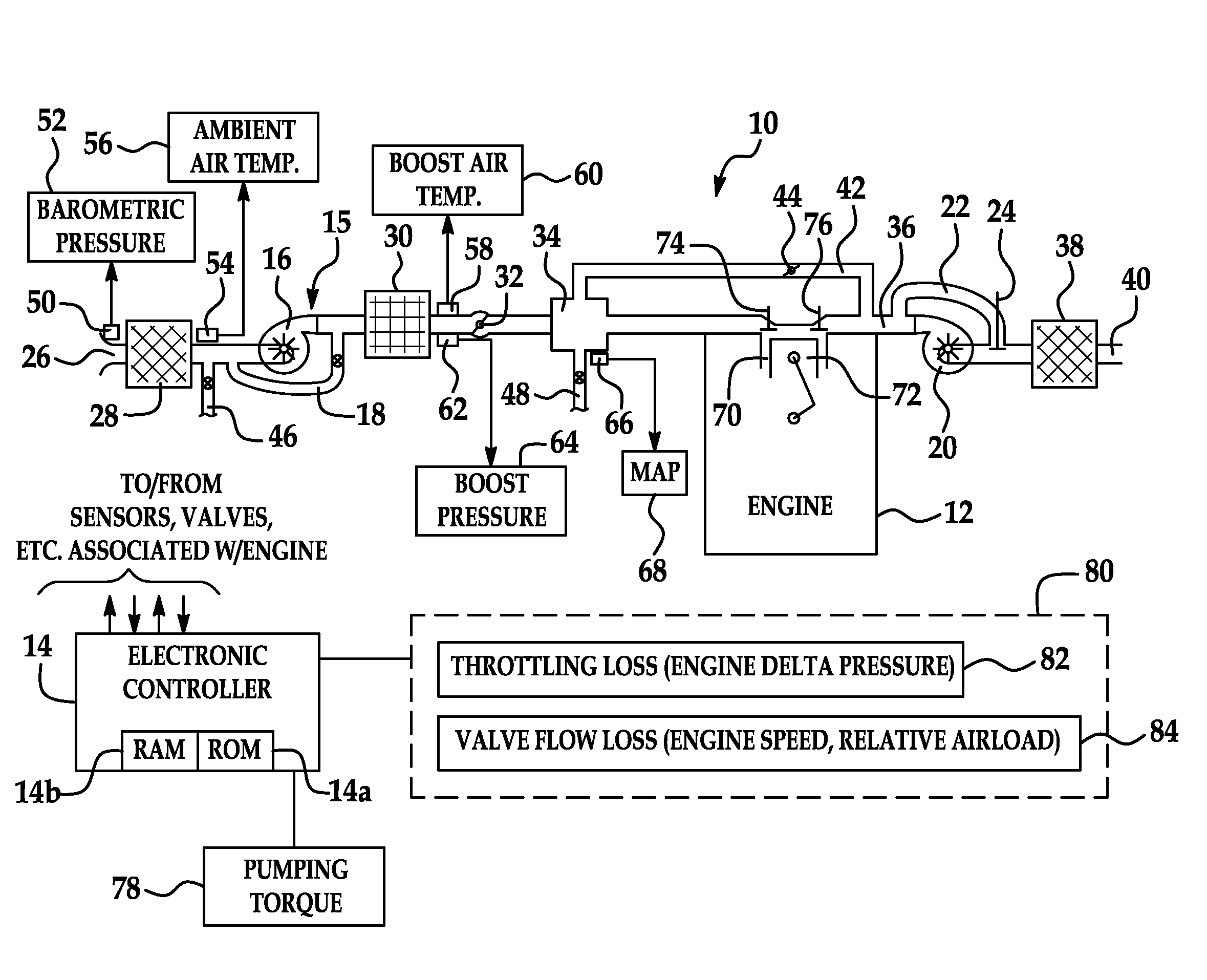
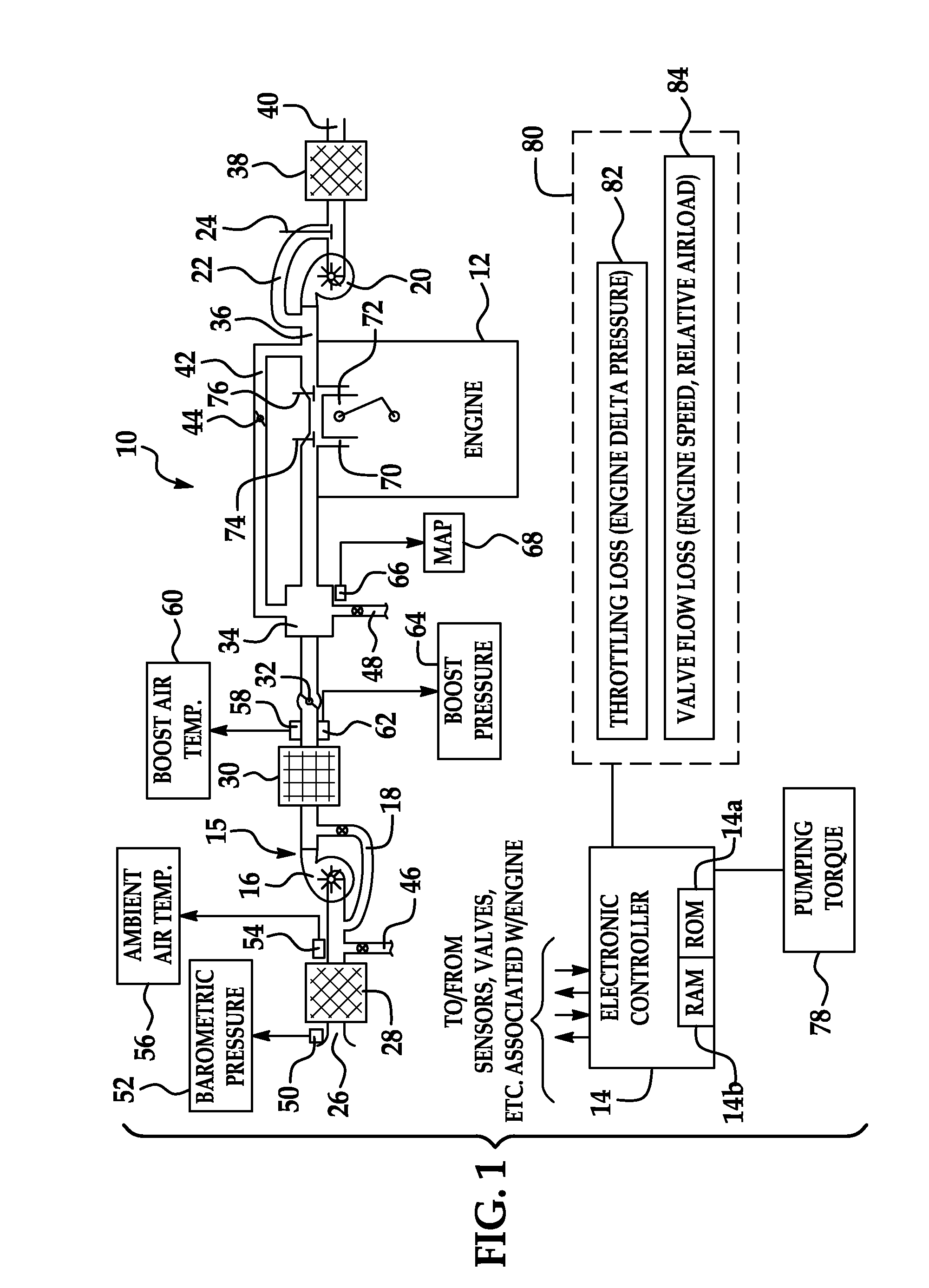
[0050]A turbo charged engine can, to an extent, at altitude recreate the same high boost and therefore load as sea level by closing the waste-gate and therefore increasing exhaust manifold pressure. The new model will properly increase the pumping loss estimate due to the increase in exhaust throttling (throttling loss table 82) while the valve flow loss contribution stays the same due to the same AIRLOAD (valve flow loss table 84).

[0051]It should be understood that electronic controller 14 as described above may include conventional processing apparatus known in the art, capable of executing pre-programmed instructions stored in an associated memory, all performing in accordance with the functionality described herein. That is, it is contemplated that the processes described herein will be programmed in a preferred embodiment, with the resulting software code being stored in the associated memory. Implementation of the present invention, in software, in view of the foregoing enabli...


PUM


Abstract

A system and method for controlling an engine involves providing a pumping torque estimation model. The model distinguishes between pumping losses due to throttling and pumping losses due to valve flow losses. The model is implemented by a pair of look-up tables. The data in each look-up table reflect Pumping Mean Effective Pressure (PMEP), which is indicative of the pumping work. The throttling loss table provides a first contribution based on an engine delta pressure. The valve flow loss table provides a second contribution based on an engine speed and a relative airload. The first and second contributions are summed and then multiplied by a predetermined factor to convert the pumping work (PMEP) into pumping torque. The model will work with naturally-aspirated, turbo-charged and super-charged air induction configurations and provides improved altitude compensation. The model will also work with both spark-ignition and compression-ignition configurations.

Description

RELATED APPLICATIONS[0001]This application claims the benefit of U.S. provisional application Ser. No. 60 / 949,269 filed Jul. 12, 2007 entitled PUMPING TORQUE ESTIMATION MODEL FOR ALL AIR INDUCTION CONFIGURATIONS AND VOLUMETRIC EFFICIENCY MODEL FOR ALL AIR INDUCTION CONFIGURATIONS, owned by the common assignee of the present invention and herein incorporated by reference in its entirety.TECHNICAL FIELD[0002]The present invention relates to a system and method for a pumping torque estimation model suitable for use with all air configurations (e.g., naturally-aspirated, turbo-charged, and super-charged) and all combustion types (i.e., spark ignition and compression ignition).BACKGROUND OF THE INVENTION[0003]It is known that in an internal combustion engine, engine pumping work is used to draw the combustion charge of fuel and air into the combustion chamber (cylinder) and to exhaust the burned gas from the cylinder. Accordingly, the net torque that is available to be delivered to the p...

Claims


Application Information

Patent Timeline
Patent Type & Authority Applications(United States)
IPC IPC(8): F02D45/00
CPCF02D41/0007F02D41/1448F02D41/1497F02D2200/1006F02D2200/0402F02D2200/0406F02D41/2432
Inventor MULLER, MARTIN
Owner DELPHI TECH INC
Why Eureka
Try Eureka