Method and apparatus for cleaning master disk

Inactive Publication Date: 2009-01-22
FUJIFILM CORP
View PDF1 Cites 7 Cited by
  • Summary
  • Abstract
  • Description
  • Claims
  • Application Information

AI Technical Summary

Benefits of technology

[0024]According to the present invention, the dust removal effect can be improved to enable removal of dust with high efficiency in comparison with the conventional method of simply performing sticking and peeling based on the adhesion of a self-adhesive material only. The present invention therefore enables effectively removing even dust firmly attached on the disk sur

Problems solved by technology

Each of the conventional techniques, however, has a drawback.
That is, CO2 cleaning is effective in removing inorganic materials but has substantially no effect in removing organic materials and leaves a watermark after cleaning.
If hard dust is generated, it is dragged on the disk surface after removal to cause a scratch on the surface.
Plasma cleaning has no metal removal effect and has a drawback in that the master surface is oxidized and the removal speed is low.
Each of scrub cleaning, ultrasonic cleaning and jet cleaning tends to damage the master surface.
E

Method used


Image

  • Method and apparatus for cleaning master disk
  • Method and apparatus for cleaning master disk
  • Method and apparatus for cleaning master disk

Examples


first embodiment

[Example of Configuration of Cleaning Apparatus]

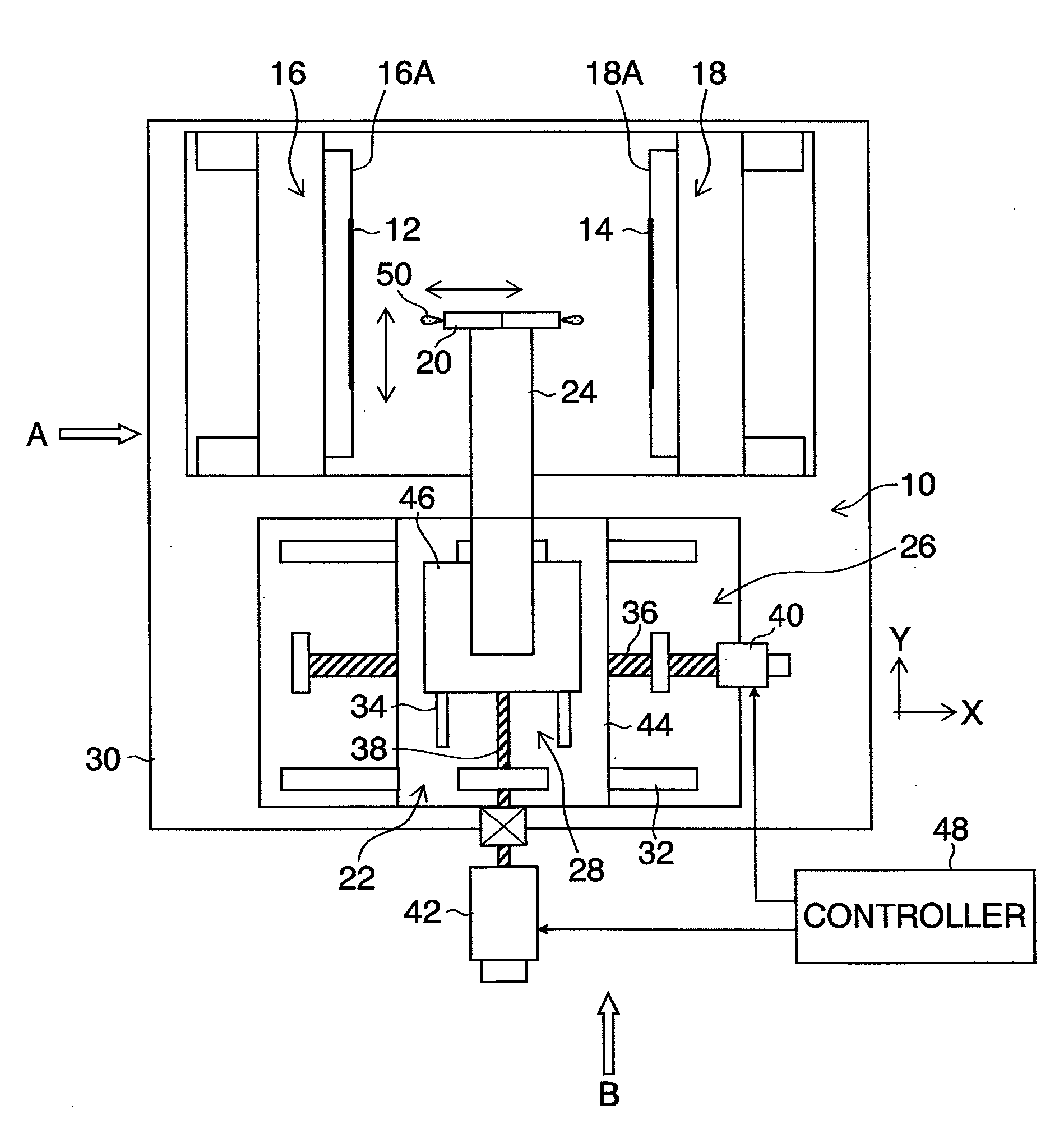
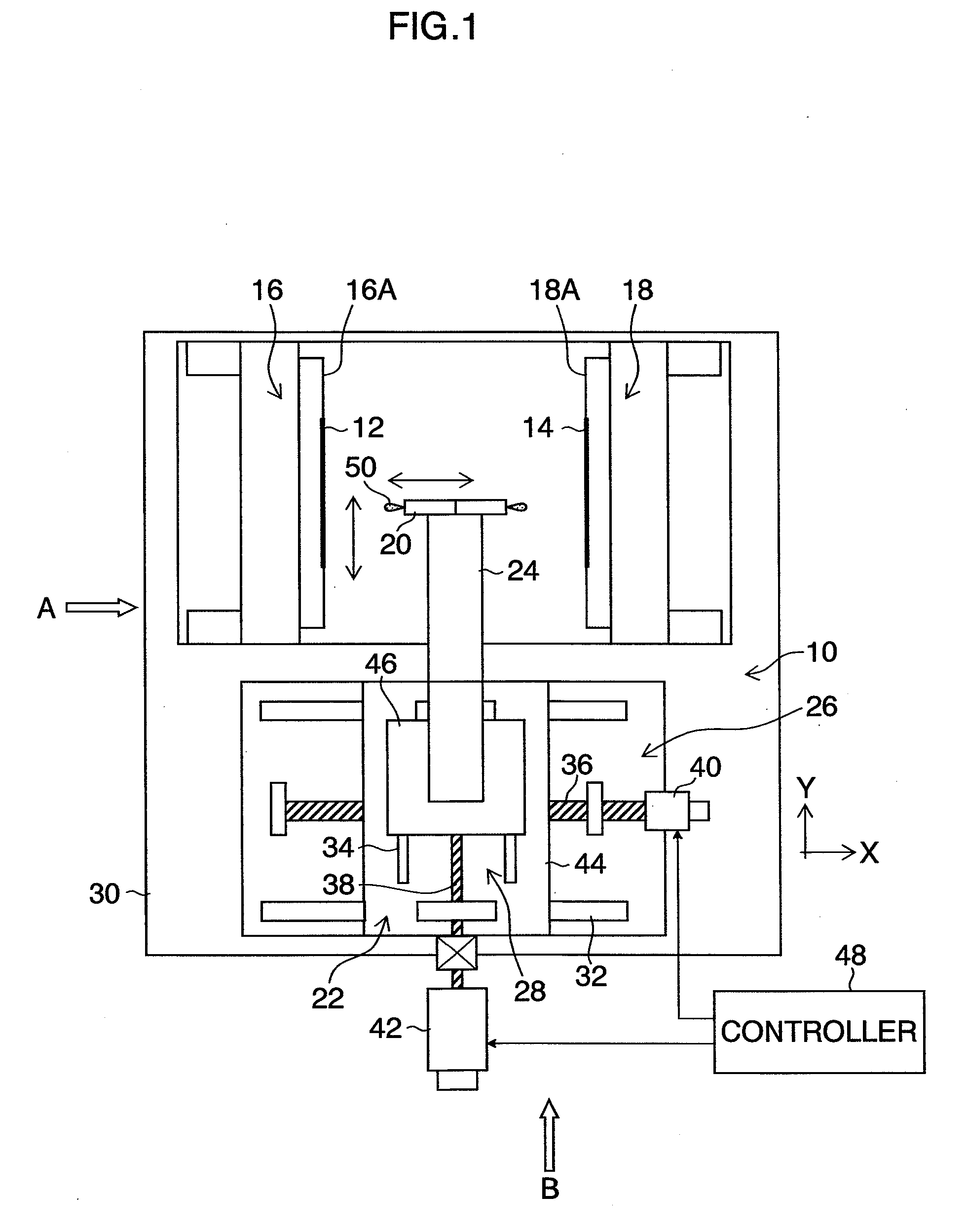
[0042]FIG. 1 is a plan view of a cleaning apparatus according to an embodiment of the present invention. FIG. 2 is a side view seen in the direction of arrow A in FIG. 1. FIG. 3 is a side view seen in the direction of arrow B in FIG. 1.

[0043]As shown in these figures, the cleaning apparatus 10 has, as its main components, holder units 16 and 18 on which master disks 12 and 14 are held, a drive unit 22 having a device for driving a cleaning head 20, and a base plate 30.

[0044]The holder units 16 and 18 have disk holding surfaces 16A and 18A on which the master disks 12 and 14 are held in a vertically upright attitude (such that the disk surface is parallel to a vertical line). The disk holding surfaces 16A and 18A of the holder units 16 and 18 face each other while being spaced apart from each other by a predetermined distance. The holder units 16 and 18 are positioned and fixed on the base plate 30.

[0045]The drive unit 22 has a first-ax...

second embodiment

[0072]A second embodiment of the present invention has a feature relating to step S118 in the flowchart representing the cleaning sequence shown in FIG. 10. More specifically, the feature relates to the operation to separate the loop 52 of the self-adhesive sheet 50 from the disk surface 12A (14A) of the master disk 12 (14) by moving the cleaning head 20 away from the master disk 12 (14). In other respects, the sequence of the second embodiment is the same or similar to the example described in the description of the first embodiment. The description of the same or similar details of the sequence will not be repeated.

[0073]With respect to step S118 shown in FIG. 10, a method of separating the loop 52 from the disk surface 12A (14A) by moving the cleaning head 20 away from the disk surface 12A (14A) directly in the direction perpendicular to the disk surface 12A (14A) is conceivable.

[0074]In the second embodiment, however, a method of separating the loop 52 from the disk surface 12A ...


PUM


Abstract

In a method of cleaning a master disk according to the present invention, a self-adhesive surface sticking/peeling operation is performed on dust on the master disk by reciprocatingly oscillating the self-adhesive member while applying external forces in a plurality of directions. Dust on the master disk can be effectively removed by moving the self-adhesive member in this way and by using the adhesion of the self-adhesive member. Since the cleaning method according to the present invention is a removal method using a physical force, it has both the effect of removing organic materials and the effect of removing inorganic materials. Further, according to the present invention, the master disk to be cleaned can be cleaned in a state of being mounted on a disk holding member such as a holder. Therefore an apparatus of a comparatively simple construction can be applied in on-line form according to the cleaning method.

Description

BACKGROUND OF THE INVENTION[0001]1. Field of the Invention[0002]The present invention relates to a method and apparatus for cleaning a master disk and, more particularly, to a cleaning technique suitable for removing dust attached to a master disk for transfer of magnetic information such as format information to a magnetic recording medium used in a hard disk unit or the like or a master disk used for nanoimprinting.[0003]2. Description of the Related Art[0004]In recent years, it has been a common practice to write format information and address information to a magnetic disk (hard disk) for use in rapidly-widespread hard disk drives before the magnetic disk is incorporated in a drive after being supplied from a magnetic disk maker to a drive maker. This writing may be performed with a magnetic head. However, a method of (magnetically) transferring such format information and address information at a time from a master disk on which the information is written is effective and prefe...

Claims


Application Information

Patent Timeline
IPC IPC(8): B08B1/02
CPCB08B1/008G11B23/505B08B7/0028
Inventor OKADA, SHINICHIRO
Owner FUJIFILM CORP
Why Eureka
Try Eureka