Method for determining local deviations of a main magnetic field of a magnetic resonance device

a magnetic resonance device and main magnetic field technology, applied in the direction of reradiation, measurement using nmr, instruments, etc., can solve the problems of unsatisfactory image data record distortion, inability to completely avoid inhomogeneity of main magnetic field of this kind, and inability to achieve the effect of avoiding distortion

Inactive Publication Date: 2009-01-22
SIEMENS HEALTHCARE GMBH
View PDF14 Cites 4 Cited by
  • Summary
  • Abstract
  • Description
  • Claims
  • Application Information

AI Technical Summary

Benefits of technology

[0012]The object of the invention is therefore to be able to determine local deviations of a ma

Problems solved by technology

Due to the dependence of Larmor frequencies on the prevailing magnetic field, inhomogeneities of the main magnetic field result in geometric distortions along the frequency encoding direction (read-out direction) in the image data records obtained from the magnetic resonance sign

Method used


Image

  • Method for determining local deviations of a main magnetic field of a magnetic resonance device
  • Method for determining local deviations of a main magnetic field of a magnetic resonance device
  • Method for determining local deviations of a main magnetic field of a magnetic resonance device

Examples


Embodiment Construction

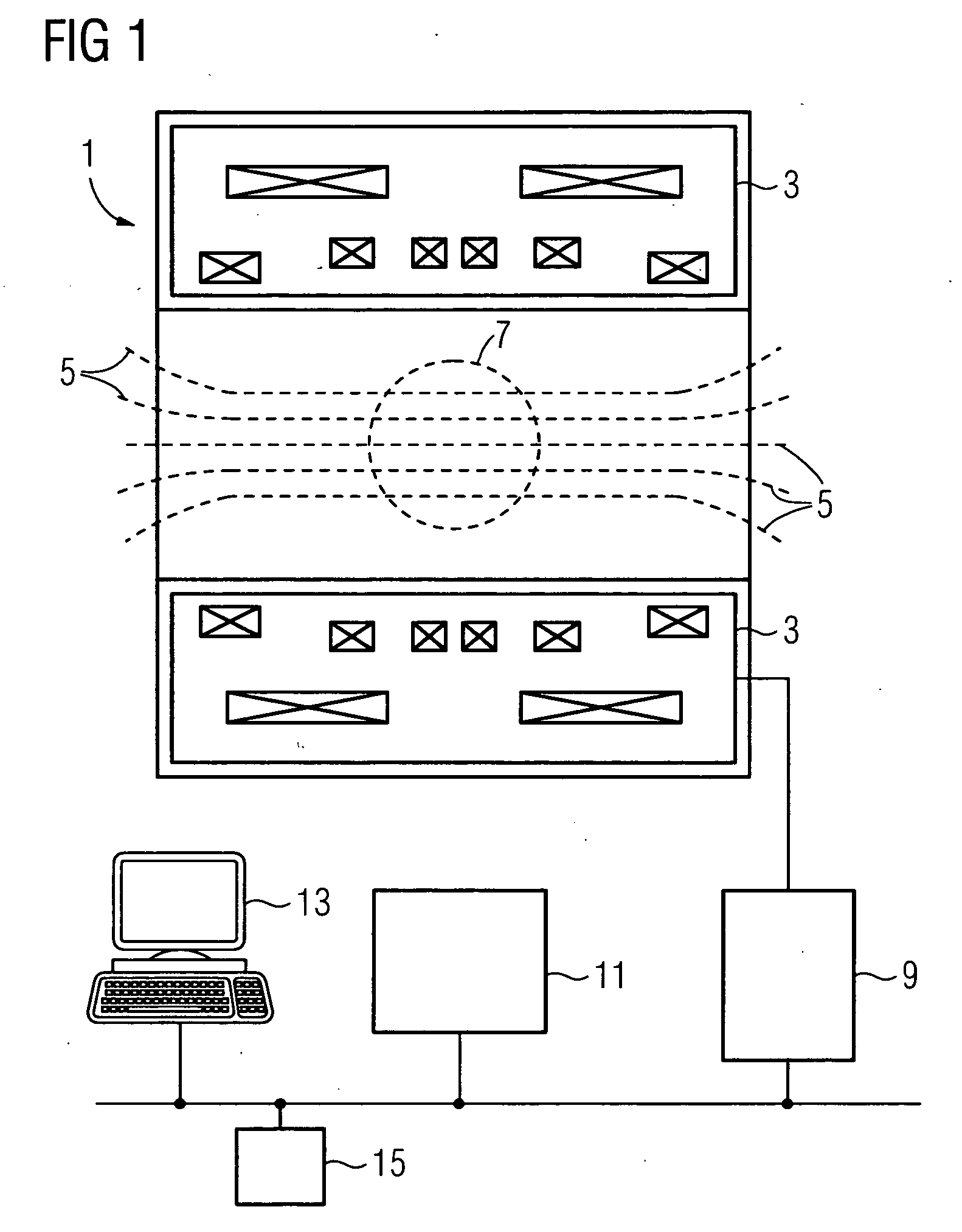
[0026]FIG. 1 is a schematic diagram of the configuration of a magnetic resonance device 1 in a side view. This only shows the parts essential for the invention. Further parts, such as, for example, a bed, local coils, gradient coils and units for controlling said device are sufficiently well known from the prior art and are not shown for purposes of clarity.

[0027]The magnetic resonance unit 1 comprises in particular a superconducting main field magnet 3. The main field magnet 3, usually a cryomagnet 3 with a tunnel-shaped opening or an open magnet, generates a strong main magnetic field 5 (shown by way of example by dashed magnetic force lines), which is usually 0.2 tesla to 3 tesla and more. Apart from small local deviations from a setpoint value, the main magnetic field 5 is homogeneous in a measuring volume 7 of the magnetic resonance device 1.

[0028]In order to examine an object by means of magnetic resonance imaging, different magnetic fields whose temporal and spatial character...


PUM


Abstract

The invention relates to a method for the determination of local deviations of a main magnetic field of a magnetic resonance device from a setpoint value, comprising: loading of a first image data record of an examination region recorded by means of the magnetic resonance device with a first frequency encoding gradient; loading of a second image data record of the same examination region recorded by means of the magnetic resonance device with a second frequency encoding gradient, with the first and the second frequency encoding gradient being different; reception of a transformation displacement field as the end result of a recording of the first and the second image data record; calculation of local deviations of the main magnetic field from a setpoint value on the basis of the calculated transformation displacement field; and display or storage of the calculated local deviations of the main magnetic field.

Description

CROSS REFERENCE TO RELATED APPLICATIONS[0001]This application claims priority of German application No. 10 2007 033 874.2 filed Jul. 20, 2007, which is incorporated by reference herein in its entirety.FIELD OF THE INVENTION[0002]The invention relates to methods for the determination of local deviations of a main magnetic field of a magnetic resonance device from a setpoint value.BACKGROUND OF THE INVENTION[0003]Magnetic resonance imaging is a known technology able to create images of the interior of an object to be examined. To do this, it employs the dependence of the precision frequencies (Larmor frequencies) of excited spins on the magnetic field strength of the prevailing magnetic field of the magnetic resonance device for local resolution. Hereby, the prevailing magnetic field comprises the main magnetic field of the magnetic resonance device and applied gradient magnetic fields. Conventional methods for the reconstruction of image data records from magnetic resonance signals r...

Claims


Application Information

Patent Timeline
IPC IPC(8): G01R33/565G01R33/56
CPCG01R33/56563G01R33/243
Inventor RITTER, DIETER
Owner SIEMENS HEALTHCARE GMBH
Why Eureka
Try Eureka