
Resin frame equipped membrane electrode assembly for fuel cell and method of producing the same

a fuel cell and membrane electrode technology, applied in the direction of final product manufacturing, sustainable manufacturing/processing, electrochemical generators, etc., can solve the problems of affecting the production efficiency of fuel cells, and forming unwanted gaps between resin frame members and contact surfaces, etc., to prevent deformation, prevent the occurrence of melting, and simple structure

Active Publication Date: 2020-05-26
HONDA MOTOR CO LTD
View PDF10 Cites 0 Cited by
  • Summary
  • Abstract
  • Description
  • Claims
  • Application Information

AI Technical Summary

Benefits of technology

The present invention aims to provide a resin frame equipped membrane electrode assembly for a fuel cell and a method of producing the assembly. The technical effects of this invention include: (a) a resin frame member with an improved seal surface that is not affected by heat during the production process and (b) a simple structure that allows for reliable and easy obtainment of a resin impregnation area with stable quality. The invention solves problems of previous methods by providing a solution to prevent deformation and melting of the resin frame member during production and ensuring the stability of the resin impregnation area.

Problems solved by technology

Therefore, deformation, melting, etc., tend to occur easily due to such heat, and the resin frame member may develop uneven surfaces, which is undesirable.
Therefore, if the resin frame member has such uneven surfaces, unwanted gaps may be formed between the resin frame member and contact surfaces (seal surfaces) of the seal members.
Consequently, leakage of reactant gases or a coolant may occur.
Therefore, depending on the shape of the resin frame member, at the time of impregnation, the load may not be applied uniformly to the impregnation portion.
Consequently, defects such as cracks, etc., may be formed in the resin frame member, and insufficient impregnation may occur.
Under such circumstances, a stable joining quality may not be obtained.

Method used


Image

  • Resin frame equipped membrane electrode assembly for fuel cell and method of producing the same
  • Resin frame equipped membrane electrode assembly for fuel cell and method of producing the same
  • Resin frame equipped membrane electrode assembly for fuel cell and method of producing the same

Examples


Embodiment Construction

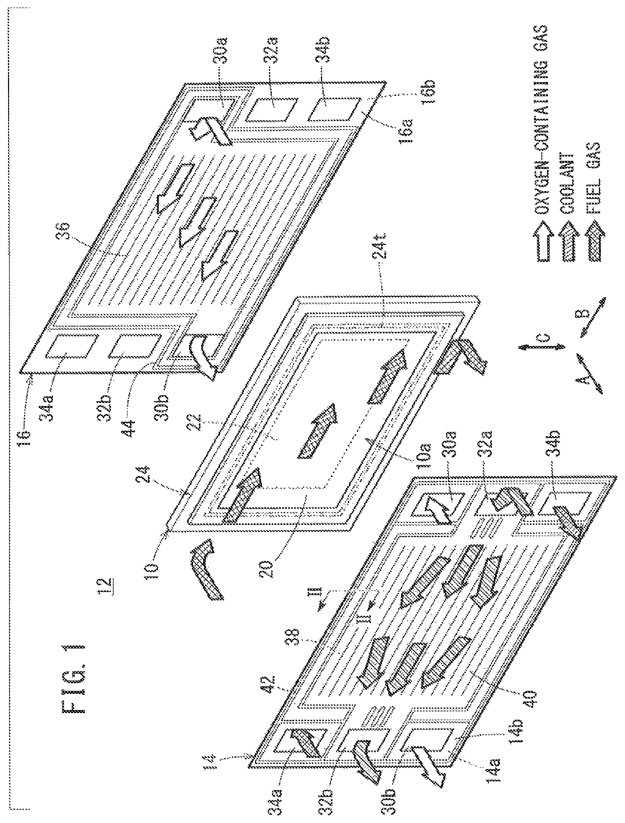
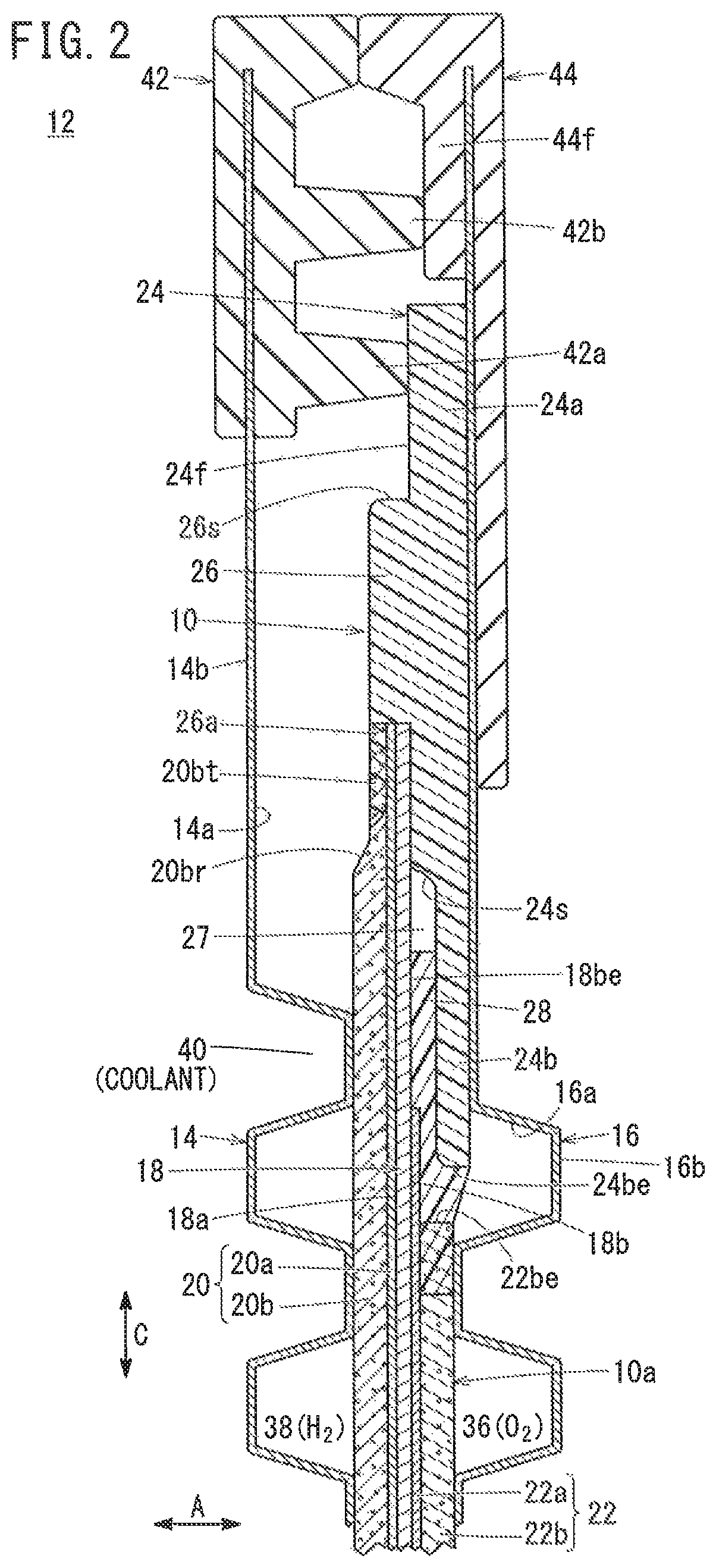
[0026]As shown in FIGS. 1 and 2, a resin frame equipped membrane electrode assembly 10 according to the embodiment of the present invention is incorporated in a laterally elongated (or longitudinally elongated) rectangular solid polymer power generation cell 12. A plurality of the power generation cells 12 are stacked together in a horizontal direction as indicated by the arrow A, or in a direction of gravity as indicated by the arrow C, in order to form a fuel cell stack. For example, the fuel cell stack is mounted in a fuel cell electric automobile (not shown) as an in-vehicle fuel cell stack.

[0027]The power generation cell 12 is formed by sandwiching the resin frame equipped membrane electrode assembly 10 between a first separator 14 and a second separator 16. Each of the first separator 14 and the second separator 16 has a laterally elongated (or longitudinally elongated) rectangular shape. For example, the first separator 14 and the second separator 16 are made of metal plates ...


PUM

PropertyMeasurementUnit
widthaaaaaaaaaa
surface sizeaaaaaaaaaa
circumferenceaaaaaaaaaa

Abstract

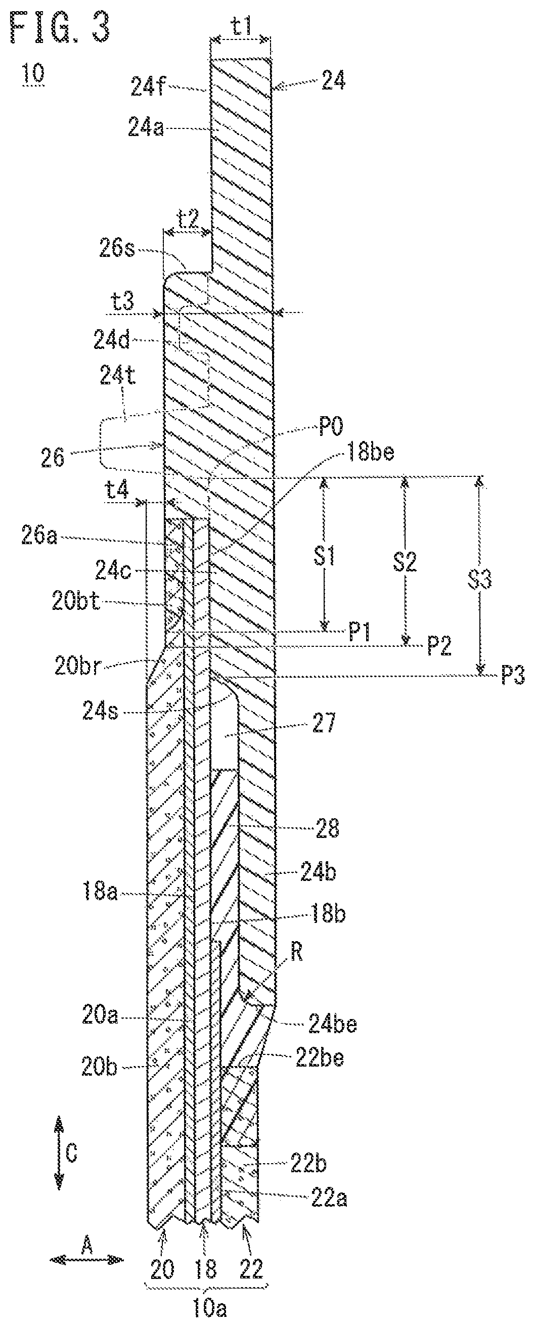
A resin frame equipped membrane electrode assembly includes an MEA having different sizes of components, and a resin frame member. A resin melt portion is provided for the resin frame member. The inside of a first gas diffusion layer is impregnated with resin as a part of the resin melt portion. A thin portion is provided at an outermost peripheral portion of the resin frame member through a step at an outermost peripheral portion of the resin melt portion, and the thin portion is thinner in a thickness direction than the resin melt portion.

Description

CROSS-REFERENCE TO RELATED APPLICATIONS[0001]This application is based upon and claims the benefit of priority from Japanese Patent Applications No. 2015-207259 filed on Oct. 21, 2015, and No. 2015-208423 filed on Oct. 22, 2015, the contents all of which are incorporated herein by reference.BACKGROUND OF THE INVENTIONField of the Invention[0002]The present invention relates to a resin frame equipped membrane electrode assembly for a fuel cell. The resin frame equipped membrane electrode assembly includes an MEA having different sizes of components, i.e., an MEA including a solid polymer electrolyte membrane and a first electrode and a second electrode having different surface sizes sandwiching the solid polymer electrolyte membrane therebetween. The resin frame equipped membrane electrode assembly includes a resin frame member provided around the outer periphery of the MEA. Further, the present invention relates to a method of producing the resin frame equipped membrane electrode as...

Claims


Application Information

Patent Timeline
Patent Type & Authority Patents(United States)
IPC IPC(8): H01M8/0273H01M8/0284H01M8/0286H01M8/1004H01M8/1018
CPCH01M8/0284H01M8/0286H01M8/1018H01M8/0273H01M8/1004Y02E60/521Y02T90/32H01M2008/1095H01M2250/20Y02E60/50Y02P70/50Y02T90/40
Inventor OHMORI, SUGURUTANAKA, YUKIHITOKIMURA, YOSHIHITOFUJITSUKA, RYUGOTANAKA, SHINTAROTANI, MASAKI
Owner HONDA MOTOR CO LTD
Learn More