Radar device

a technology of a radar and a target angle, applied in the direction of measurement devices, using reradiation, instruments, etc., can solve the problem of not being able to obtain information indicating whether a target angle (defining the front direction as 0 degrees) is positive or negativ

Active Publication Date: 2009-01-22
MITSUBISHI ELECTRIC CORP
View PDF10 Cites 21 Cited by
  • Summary
  • Abstract
  • Description
  • Claims
  • Application Information

AI Technical Summary

Benefits of technology

[0013]According to the present invention, even when only a real signal can be obtained as a received signal, it can be determined whether the sign of the Doppler frequency or the target angle is positive or negative.

Problems solved by technology

Furthermore, when a DBF-system antenna is used, information indicating whether a target angle (defining the front direction as 0 degree) is positive or negative cannot be obtained.

Method used


Image

  • Radar device
  • Radar device
  • Radar device

Examples


first embodiment

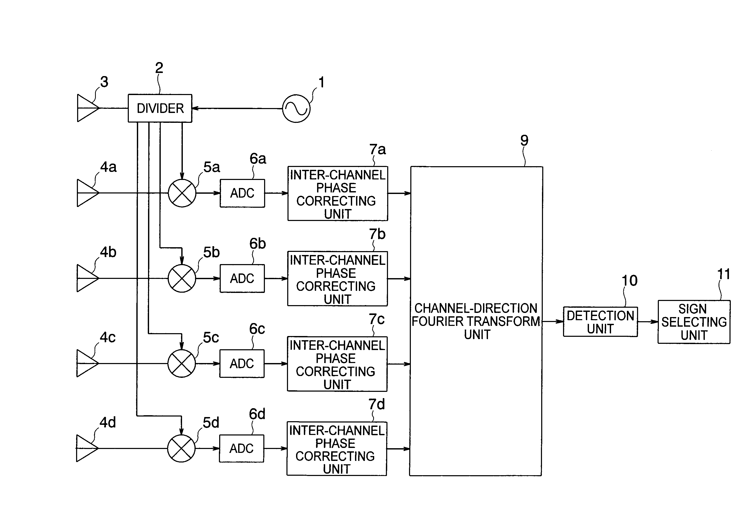
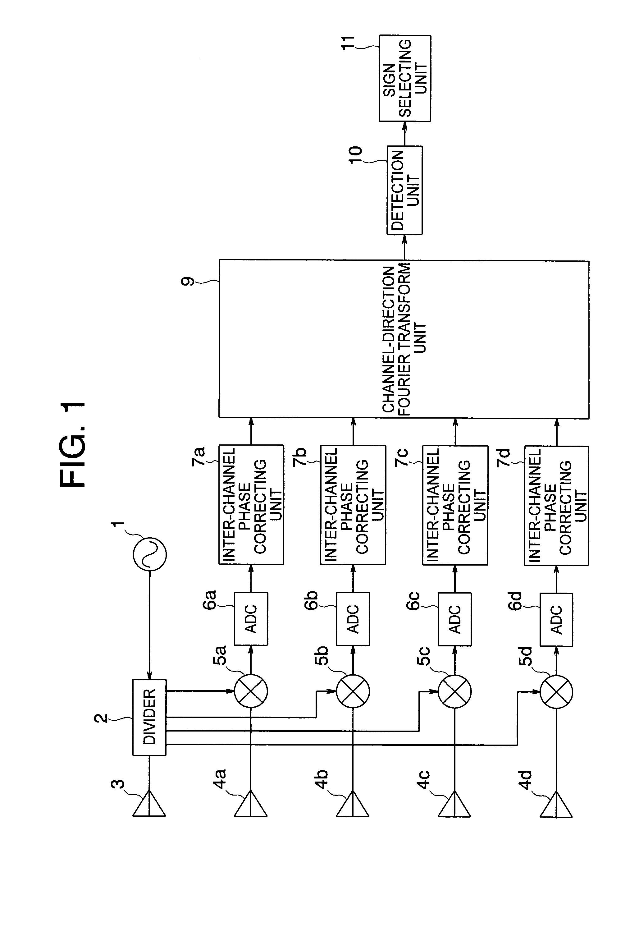
[0025]FIG. 1 is a block diagram illustrating a configuration of a radar device according to a first embodiment of the present invention. The radar device illustrated in FIG. 1 includes an oscillator 1, a divider 2, a transmitting antenna 3, a plurality of receiving antennas 4a to 4d, a plurality of receivers 5a to 5d, a plurality of A / D converters 6a to 6d, and a plurality of inter-channel phase correcting units 7a to 7d. The oscillator 1 generates a transmission wave (wave). The divider 2 serves as a local wave extracting unit which divides the transmission wave output from the oscillator 1 to extract a part of the transmission waves obtained by the division as a local wave. The transmitting antenna 3 serves as a transmitting element. One of the transmission waves output from the divider 2 is input to the transmitting antenna 3, which in turn emits the transmission wave into space. The plurality of receiving antennas 4a to 4d are receiving elements located at the positions differen...

second embodiment

[0061]In the first embodiment described above, the Fourier transform is performed only in the channel direction. In the embodiment described below, the Fourier transform is also performed in a time direction.

[0062]FIG. 4 is a block diagram illustrating a configuration of a radar device according to the second embodiment of the present invention. In the configuration illustrated in FIG. 4 according to the second embodiment, the same components as those of the configuration illustrated in FIG. 1 according to the first embodiment are denoted by the same reference numerals, and the description thereof is herein omitted. The configuration illustrated in FIG. 4 according to the second embodiment differs from that illustrated in FIG. 1 according to the first embodiment in that time-direction Fourier transform units 8a to 8d are further provided between the plurality of inter-channel phase correcting units 7a to 7d and the channel-direction Fourier transform unit 9. Each of the time-directi...

third embodiment

[0072]In the above-described embodiments, an inter-channel phase variation generated in the fabrication process or due to a change with time is corrected to solve the problem of ambiguity in sign in the measurement. However, when the radar device can be fabricated with high accuracy and a change with time can be estimated to be small, it is conceivable to give an inter-channel phase variation in advance to design and fabricate the radar device. Such an embodiment will now be described below.

[0073]FIG. 9 is a block diagram illustrating a configuration of a radar device according to a third embodiment of the present invention. In the configuration illustrated in FIG. 9 according to the third embodiment, the same components as those of the configuration illustrated in FIG. 1 according to the first embodiment are denoted by the same reference numerals, and the description thereof is herein omitted. The third embodiment illustrated in FIG. 9 differs from the first embodiment illustrated ...


PUM


Abstract

For enabling determination on whether a sign of a Doppler frequency or a target angle is positive or negative even when only a real signal can be obtained as a received signal, the present invention provides a radar device including: an oscillator; a transmitting element; a distributor; receivers using the local wave to detect the received wave to generate a real received signal; a plurality of inter-channel phase correcting units; a spatial frequency information generating unit for converting a received signal string obtained by gathering a plurality of phase-corrected received signals into a signal in a spatial frequency domain; and a sign selecting unit for selecting a signal having a larger amplitude in a spatial frequency spectrum when two signals from a positive direction and a negative direction which are symmetrical with respect to a direction at approximately 0 degree.

Description

BACKGROUND OF THE INVENTION[0001]1. Field of the Invention[0002]The present invention relates to a radar device for emitting a wave into space, receiving the wave reflected by an object present in the space, and performing signal processing on the received wave to measure the object.[0003]2. Description of the Related Art[0004]Generally, a radar emits an electromagnetic wave into space and receives the electromagnetic wave reflected by a target present in the space to know the presence / absence of the target, specifically, to detect the target. When the target moves relative to the radar, measurement of a frequency shift caused by a Doppler effect, specifically, measurement of a Doppler frequency also allows measurement of a relative velocity of the target, specifically, a Doppler velocity.[0005]For the measurement of the Doppler frequency, an I / Q detection system for obtaining two orthogonal signal components as received signals is generally used. According to this detection system,...

Claims


Application Information

Patent Timeline
Patent Type & Authority Applications(United States)
IPC IPC(8): G01S13/00
CPCG01S7/354G01S2007/358G01S2007/356G01S13/584G01S7/356G01S7/358
Inventor WAKAYAMA, TOSHIOMITSUMOTO, MASASHIUEHARA, NAOHISA
Owner MITSUBISHI ELECTRIC CORP
Why Eureka
Try Eureka