Droplet discharge head and droplet discharge device

a technology of droplet discharge and droplet, which is applied in the direction of printed circuits, typewriters, printing, etc., can solve the problems of reducing the productivity of various patterns, reducing the efficiency of various patterns, and increasing the heat load imposed on the circuit pattern and the green sheet, so as to achieve stable dried-state droplets, increase the irradiation time, and the effect of reducing the degradation of the performance of the droplet discharging treatmen

Active Publication Date: 2009-01-22
SEIKO EPSON CORP
View PDF4 Cites 4 Cited by
  • Summary
  • Abstract
  • Description
  • Claims
  • Application Information

AI Technical Summary

Benefits of technology

[0010]An advantage of the present invention is to provide a droplet discharge head and a droplet discharge device that increase an irradiation time with light without degrading performance of a droplet discharging treatment so as to provide a stable dried-state to droplets.
[0011]A droplet discharge head according to a first aspect of the invention includes: a head body having a surface opposed to an object; a plurality of nozzles aligned on the surface and discharging a droplet to each of positions of the object; and an irradiation part disposed on the surface and irradiating the object with light. In the droplet discharge head, the irradiation part includes i×j pieces of irradiation parts arranged such that i (an integer number of 1 or more) pieces of irradiation parts are aligned in an alignment direction of the nozzles and j (an integer number of 2 or more) pieces of irradiation parts are disposed in a predetermined direction that is orthogonal to the alignment direction of the nozzles and aligned along the predetermined direction.
[0012]According to the droplet discharge head of the first aspect, when the droplet discharge head and the object relatively move in the predetermined direction, a droplet that is discharged from a nozzle is irradiated with light emitted from j pieces of irradiation parts. Therefore, in a coordinate space along the predetermined direction, irradiation time for a droplet is increased in accordance with j, that is, the number of irradiation parts. Accordingly, the droplet discharge head can increase the irradiation time of light independently from the relative-moving velocity thereof with respect to the object and the spot size of light. The droplet discharge head can conduct an irradiation of light having low energy with respect to the droplet for a long period of time, preventing bumping and a lack of drying of the droplet. Therefore, the droplet discharge head can provide a stable drying state to the droplet without degrading performance in the droplet discharge treatment.
[0013]In the droplet discharge head of the first aspect, the irradiation parts may include: first irradiation parts disposed in the predetermined direction of the nozzles and irradiating a first part of a line that passes through one of the positions opposed to the nozzles and extends along the predetermined direction with the light, and second irradiation parts disposed in the predetermined direction of the first irradiation parts and irradiating a second part that is different from the first part on the line with the light.
[0014]According to the droplet discharge head of the first aspect, when the droplet discharge head and the object relatively move in the predetermined direction, a droplet that is discharged from a nozzle passes through the first part and the second part of the line. Therefore, in a coordinate space along the predetermined direction, an irradiation time for a droplet is increased in accordance with the number of the first irradiation part and the second irradiation parts. As a result, the droplet discharge head can conduct an irradiation of light having low energy with respect to the droplet for a long period of time. Therefore, the droplet discharge head can provide a stable drying state to the droplet without degrading performance in the droplet discharge treatment.
[0015]In the droplet discharge head of the first aspect, it is preferable that the light be laser light, the first irradiation parts be mounted on the surface and include first vertical cavity surface emitting lasers emitting the laser light, and the second irradiation parts be mounted on the surface and include second vertical cavity surface emitting lasers emitting the laser light.

Problems solved by technology

However, if the circuit pattern made from droplets is dried in a dry furnace, a heating treatment is conducted on the whole of the green sheet, increasing a heat load imposed on the circuit pattern and the green sheet.
However, irradiation of laser light having high energy with respect to the droplets of several to several dozen picoliters causes bumping of the droplets instantly, eliminating the circuit pattern near the droplets.
Therefore, productivity of various patterns is substantially degraded.
As a result, the droplet discharge head can conduct an irradiation of light having low energy with respect to the droplet for a long period of time.
As a result, the droplet discharge device can irradiate the droplet with light having low energy for a long period of time.

Method used


Image

  • Droplet discharge head and droplet discharge device
  • Droplet discharge head and droplet discharge device
  • Droplet discharge head and droplet discharge device

Examples


first embodiment

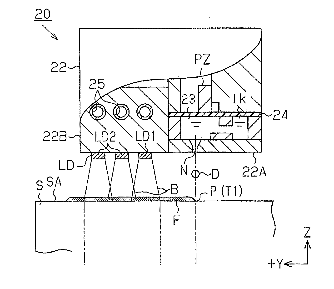
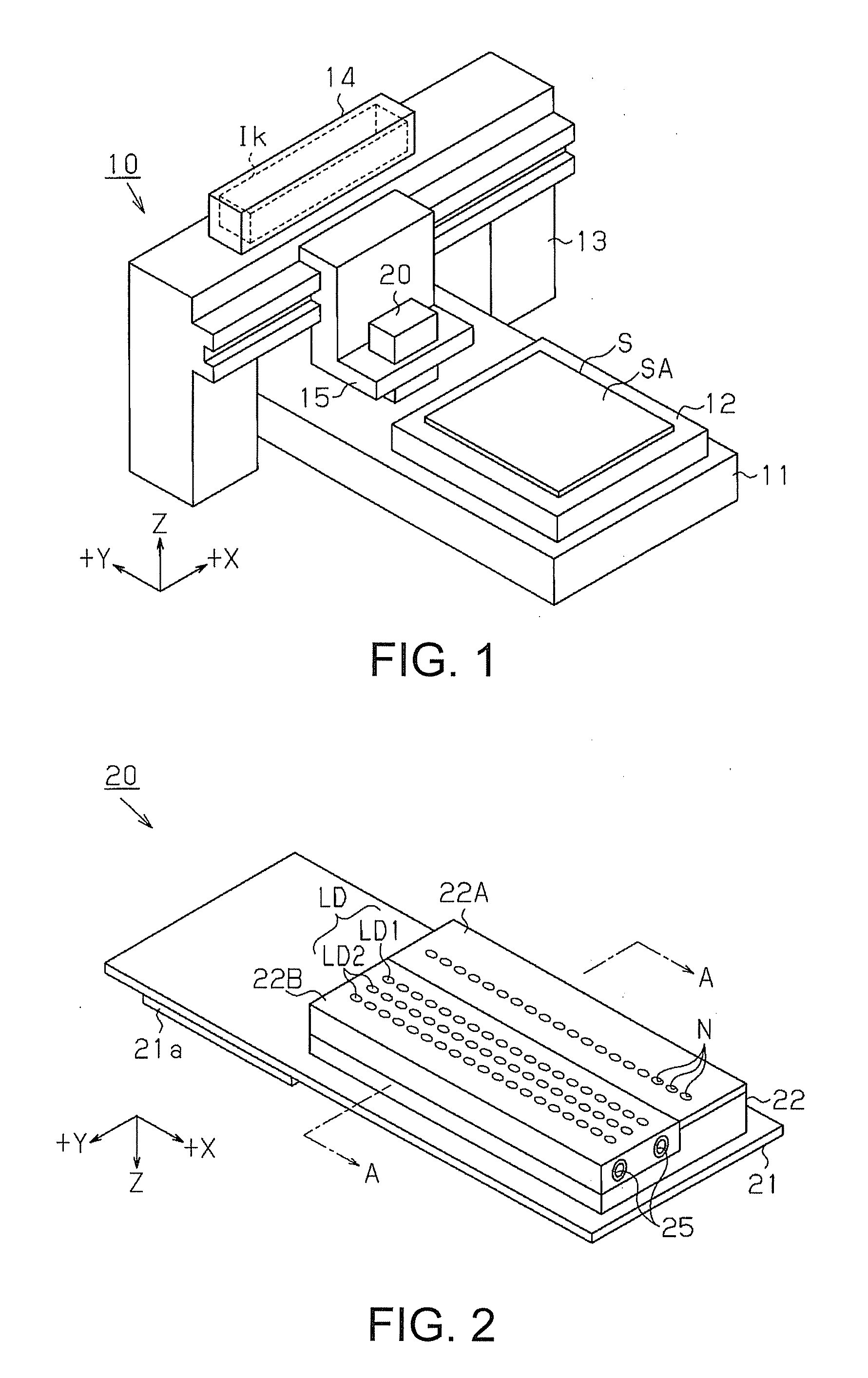
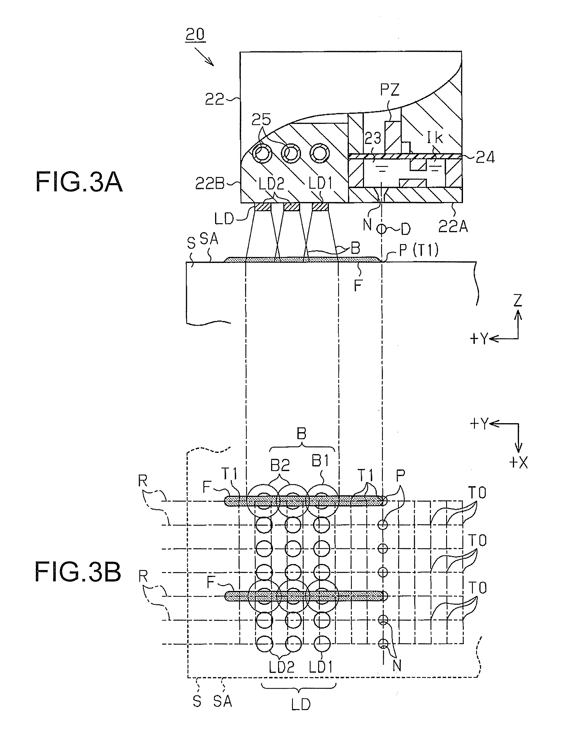
[0055]A first embodiment of the invention will be described below with reference to FIGS. 1 to 5. FIG. 1 is a perspective view showing a droplet discharge device 10.

[0056]Referring to FIG. 1, the droplet discharge device 10 includes a base 11 extending in one direction and a stage 12 mounted on the base 11 and placing a substrate S thereon. The stage 12 positions and fixes the substrate S in a manner allowing one surface of the substrate S to face up so as to move the substrate S along a longitudinal direction of the base 11. Various kinds of substrate such as a green sheet, a glass substrate, a silicon substrate, a ceramic substrate, a resin film, a paper, and the like may be used as the substrate S.

[0057]In the first embodiment, an upper surface of the substrate S is called a discharge surface SA. A direction along which the substrate S is moved, that is, a direction toward upper left in FIG. 1 is referred to as +Y direction. A direction orthogonal to +Y direction, that is, a dire...

second embodiment

[0108]A second embodiment of the invention will be described below with reference to FIG. 6. In this second embodiment, the first lasers LD1 and the second lasers LD2 of the first embodiment are altered. Therefore, the alteration will be mainly described in detail. Elements that are common to the first embodiment are indicated by the same reference numerals.

[0109]Referring to FIG. 6, the first laser LD1 has a first micro lens ML1 having a hemisphere face as a first optical system, and the second laser LD2 has a second micro lens ML2 also having a hemisphere face as a second optical system.

[0110]When the first laser LD1 emits the first laser light B1, the first micro lens ML1 narrows the emission angle of the first laser light B1 so as to focus the light on the first part. When the second laser LD2 emits the second laser light B2, the second micro lens ML1 narrows the emission angle of the second laser light B2 so as to focus the light on the second part. The energy density of the fi...

third embodiment

[0116]A third embodiment of the invention will be described below with reference to FIG. 7. In the third embodiment, the second micro lens ML2 of the second embodiment is altered. Therefore, the alteration will be mainly described in detail. Elements that are common to the first embodiment are indicated by the same reference numerals.

[0117]Referring to FIG. 7, the second micro lens ML2 has an optical face at a closer position to the discharge surface SA than the first micro lens ML1 and has higher light focusing rate than the first micro lens ML1.

[0118]When the second laser LD2 emits the second laser light B2, the second micro lens ML2 narrows the emission angle of the second laser light B2 so as to focus the light on the second part. The energy density of the second laser light B2 that is focused is higher than that of the first laser light B1 and is set to cause no bumping of the droplet D in the second part and to encourage the droplet D in the second part to be dried.

[0119]The d...


PUM


Abstract

A droplet discharge head includes: a head body having a surface opposed to an object; a plurality of nozzles aligned on the surface and discharging a droplet to each of positions of the object; and an irradiation part disposed on the surface and irradiating the object with light. In the droplet discharge head, the irradiation part includes i×j pieces of irradiation parts arranged such that i (an integer number of 1 or more) pieces of irradiation parts are aligned in an alignment direction of the nozzles and j (an integer number of 2 or more) pieces of irradiation parts are disposed in a predetermined direction that is orthogonal to the alignment direction of the nozzles and aligned along the predetermined direction.

Description

BACKGROUND[0001]1. Technical Field[0002]The present invention relates to a droplet discharge head and a droplet discharge device.[0003]2. Related Art[0004]Multi-layered substrates made of low temperature co-fired ceramics (LTCC) are widely used for a substrate of a high frequency module, a substrate of an IC package, and the like due to their excellent high-frequency property and high heat-resistance. In a method for manufacturing an LTCC multi-layered substrate, a step in which a circuit pattern is drawn on a green sheet with a metal ink and a step in which a plurality of green sheets are layered so as to be fired all together are commonly conducted.[0005]In terms of the step in which a circuit pattern is drawn, JP-A-2005-57139, as a first example, discloses an ink-jet method in which a metal ink is discharged as fine droplets for densifying the circuit pattern. By the ink-jet method, one circuit pattern is drawn with a lot of droplets. A bulk of one droplet is several to several d...

Claims


Application Information

Patent Timeline
Patent Type & Authority Applications(United States)
IPC IPC(8): B41J2/14
CPCB41J11/002B41J3/28B41J11/00218H05K3/125H05K3/1283H05K3/4629H05K2203/107
Inventor MIURA, HIROTSUNA
Owner SEIKO EPSON CORP
Why Eureka
Try Eureka