Display control device, imaging device, and printing device

a control device and control panel technology, applied in the field of display control devices, can solve the problems of user discomfort when viewing images, and achieve the effect of convenient viewing for users

Active Publication Date: 2009-01-22
PANASONIC INTELLECTUAL PROPERTY CORP OF AMERICA
View PDF11 Cites 9 Cited by
  • Summary
  • Abstract
  • Description
  • Claims
  • Application Information

AI Technical Summary

Benefits of technology

[0011]It is an object of the present invention to provide a display control device, an imaging device, and a prin...

Problems solved by technology

With a conventional thumbnail display, however, because the direction in which the panned images are aligned does not necessarily coincide with the direction i...

Method used


Image

  • Display control device, imaging device, and printing device
  • Display control device, imaging device, and printing device
  • Display control device, imaging device, and printing device

Examples


first embodiment

[0061]Overall Configuration of Digital Camera

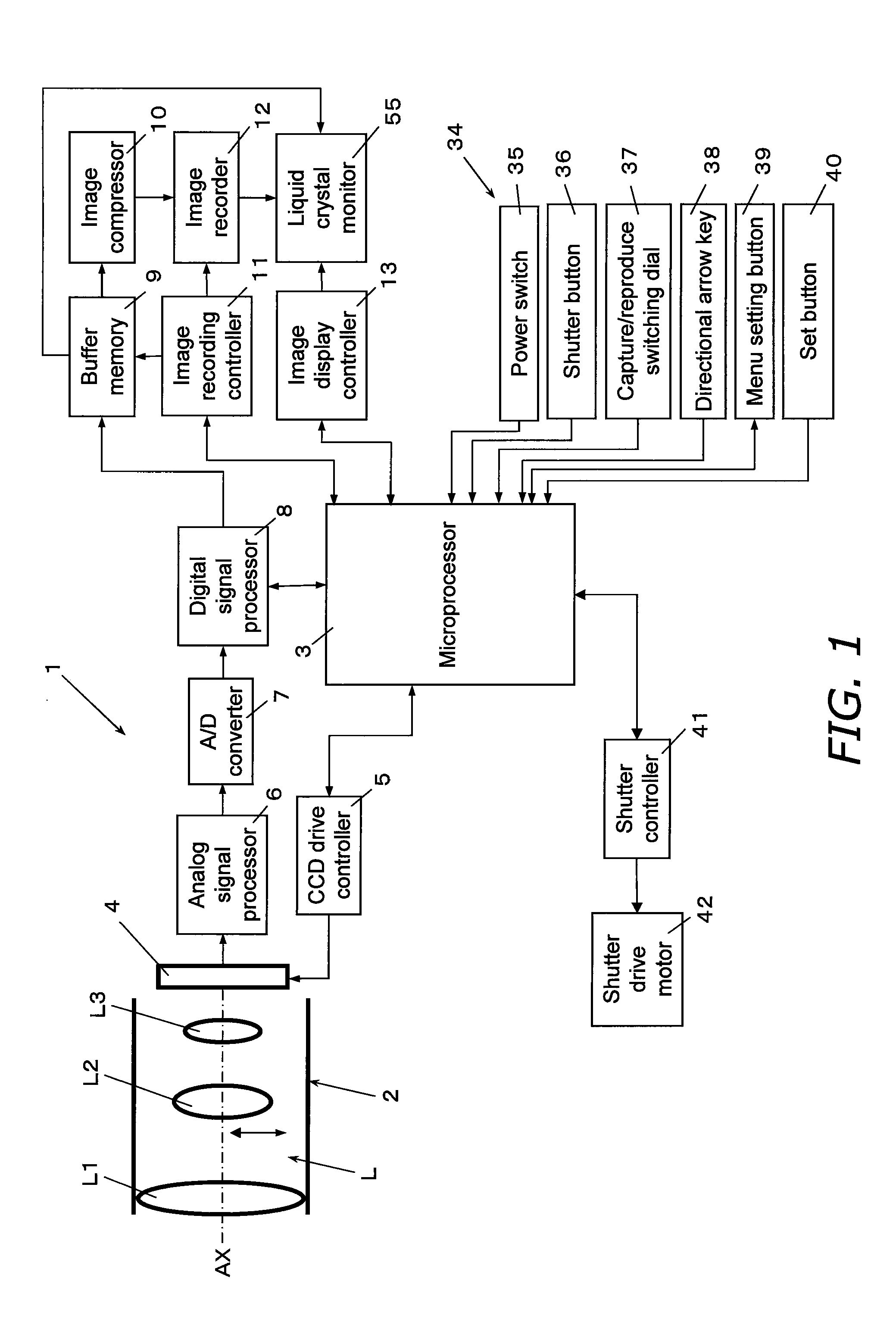
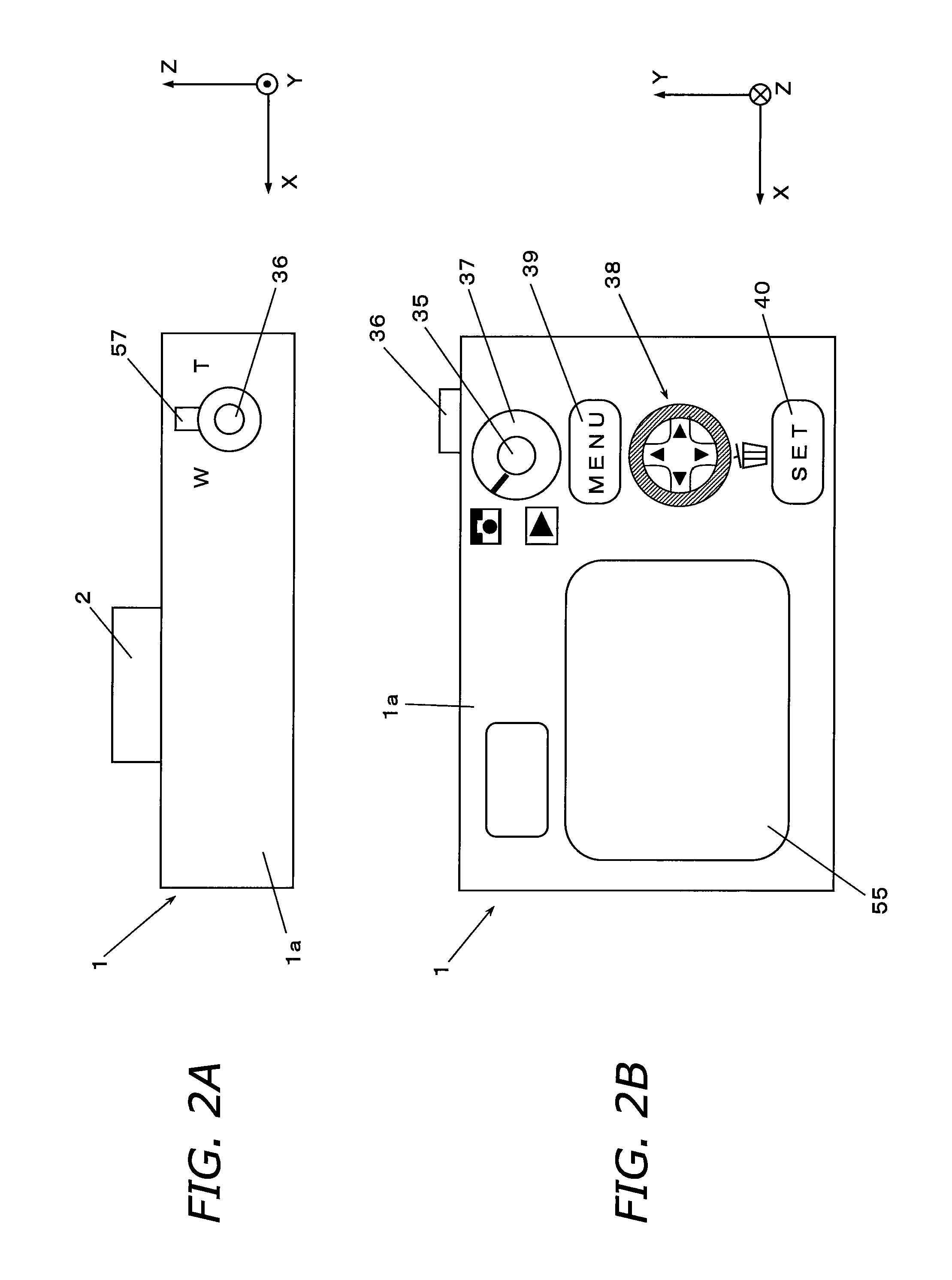
[0062]The digital camera 1 according to the first embodiment of the present invention will be described through reference to FIGS. 1 and 2. FIG. 1 is a block diagram of the simplified configuration of the digital camera 1. FIG. 2A is a top view of the digital camera 1, and FIG. 2B is a rear view of the digital camera 1. As shown in FIGS. 2A and 2B, we will let the Z axis direction be the direction along the optical axis AX of the digital camera 1, the X-axis direction the left and right direction of the digital camera 1, and the Y-axis direction the up and down direction of the digital camera 1. These directions do not limit how the digital camera 1 is used.

[0063]As shown in FIG. 1, the digital camera 1 has an imaging optical system L, a microprocessor 3, an imaging sensor 4, a CCD drive controller 5, a shutter controller 41, and a shutter drive motor 42.

[0064]The imaging optical system L is an optical system for forming an optical image ...

second embodiment

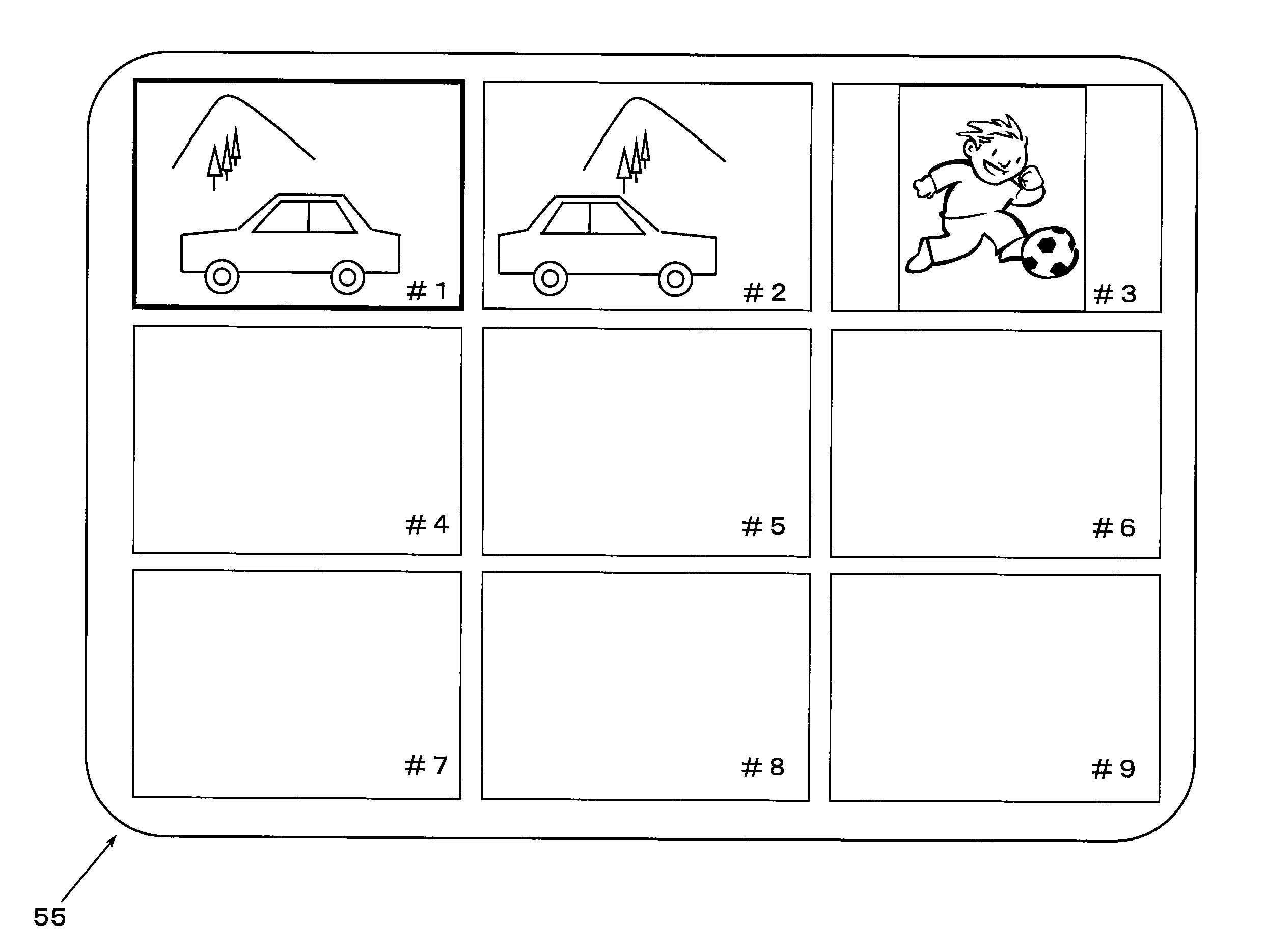
[0178]In the embodiment given above, a case was described of panning the digital camera 1 to capture images sequentially. However, as shown in FIG. 26, it is also conceivable that sequential images of a moving subject are captured without panning the digital camera 1. FIG. 27 is a block diagram illustrating an example of the configuration of a movement detector. Those components that have substantially the same function as in the above embodiment are numbered the same, and will not be described again.

[0179]As shown in FIG. 26, the state of the photography posture of the digital camera 1 in the second embodiment indicates a situation in which images are sequentially captured over a wide angle of view, over an automobile moving to the left, with the photography view angle of the digital camera 1 in substantially the same state. Here, instead of the panning mode signal 60 used in the first embodiment, the layout of images is determined on the basis of the movement vector of the subject...

third embodiment

[0187]In the above embodiments, the images were displayed on the liquid crystal monitor 55, but as shown in FIG. 28, it is also conceivable that the images are displayed on a display device 70 connected to the digital camera 1.

[0188]In this case, the only difference is that the display component has been changed from the liquid crystal monitor 55 to the display device 70 (a television monitor or the like), and this embodiment is the same as those given above in that the microprocessor 3 determines the display state and layout of the images on the basis of the panning mode signal 60, the posture determination signal 61, the movement vector signal 62, or other such information. The display device 70 is connected to the digital camera 1 via a cable 75. The cable 75 is, for example, a USB (Universal Serial Bus) cable.

[0189]The above configuration is effect when no display component is provided to the digital camera, or when the images are to be displayed in a larger size. This makes pos...


PUM


Abstract

A digital camera 1 has an image recorder 12, a microprocessor 3, and an image display controller 13. The image recorder 12 records a plurality of sequentially captured images along with a panning mode signal 60 related to the panning operation of the digital camera 1. The microprocessor 3 determines the layout of the plurality of images on the basis of the panning mode signal 60 recorded to the image recorder 12. The image display controller 13 displays a plurality of images side by side on a liquid crystal monitor 55 on the basis of the determination result of the microprocessor 3.

Description

CROSS-REFERENCE TO RELATED APPLICATIONS[0001]This application claims priority to Japanese Patent Application No. 2007-187765 filed on Jul. 19, 2007. The entire disclosure of Japanese Patent Application No. 2007-187765 is hereby incorporated herein by reference.BACKGROUND OF THE INVENTION[0002]1. Field of the Invention[0003]The present invention relates to a display control device, and more particularly to a display control device with which a plurality of images can be displayed side by side.[0004]2. Background Information[0005]The integration of signal processing and imaging sensors has been on the rise in recent years in CCDs (Charge Coupled Devices), CMOSs (Complementary Metal-Oxide Semiconductors), and so forth, and these products can now be provided inexpensively. Because of this, there has been a surge in the popularity of digital cameras and digital video cameras (hereinafter referred to simply as digital cameras) with which an optical image of a subject can be converted into...

Claims


Application Information

Patent Timeline
IPC IPC(8): H04N5/222H04N5/228
CPCH04N1/00442G09G5/32H04N1/0045H04N1/00453H04N1/00461H04N1/2112H04N1/32101H04N5/23258H04N5/23261H04N5/23287H04N5/23293H04N5/765H04N5/772H04N9/8205H04N2101/00H04N2201/3247H04N2201/3252H04N2201/3277G06K15/02H04N1/00448H04N23/6812H04N23/6815H04N23/687H04N23/631
Inventor YUMIKI, NAOTO
Owner PANASONIC INTELLECTUAL PROPERTY CORP OF AMERICA
Why Eureka
Try Eureka