Signal processing method, signal processing system, coefficient generating device, and digital camera

a signal processing and coefficient generation technology, applied in the direction of color signal processing circuits, instruments, image enhancement, etc., can solve the problems of insufficient number of pixels in the vertical line area, the estimation error of the fpn estimation value in the conventional method, and the inability to reduce the fpn estimation error sufficiently

Active Publication Date: 2009-01-22
NIKON CORP
View PDF9 Cites 30 Cited by
  • Summary
  • Abstract
  • Description
  • Claims
  • Application Information

AI Technical Summary

Problems solved by technology

The calculation for the FPN estimation value in conventional methods has an estimation error resulting from the influence of noise included in the calibration image other than the FPN.
However, the sufficient number of pixels in the vertical line area may not always be obtained due to reducing the release time lag or maintaining the speed of continuous shooting (for example about 128 pixels).
In this case, the FPN estimation error is not reduced sufficiently, and a vertical streak noise is generated in a FPN-corrected image.
Therefore, even if the estimation value includes an estimation error, the FPN estimation value is subtracted from the input image, and such noise as the FPN estimation error may remain in a FPN-removed image.

Method used


Image

  • Signal processing method, signal processing system, coefficient generating device, and digital camera
  • Signal processing method, signal processing system, coefficient generating device, and digital camera
  • Signal processing method, signal processing system, coefficient generating device, and digital camera

Examples


first embodiment

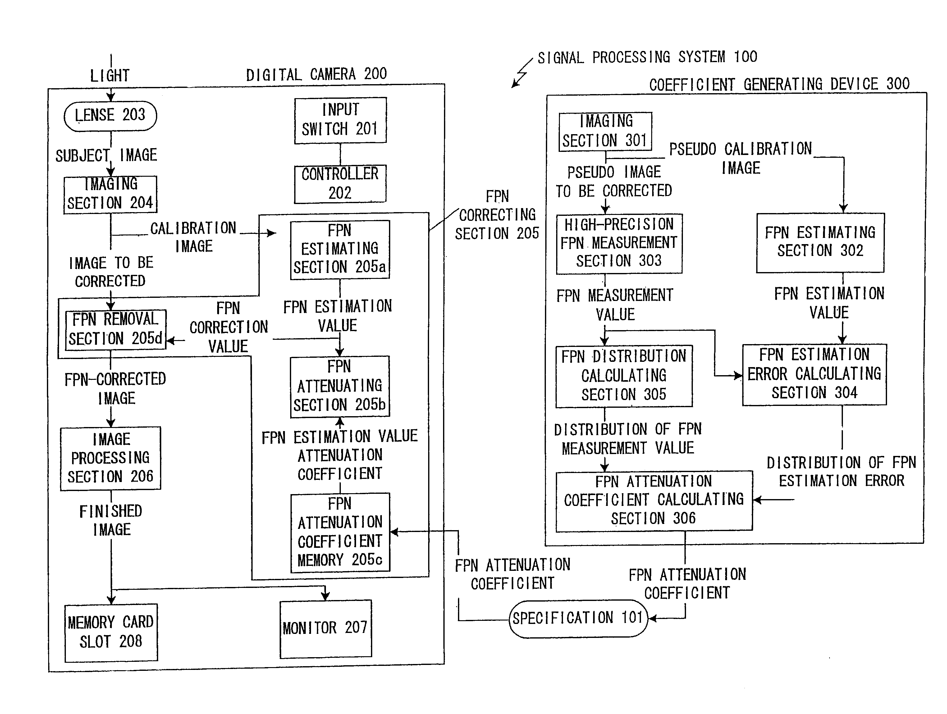
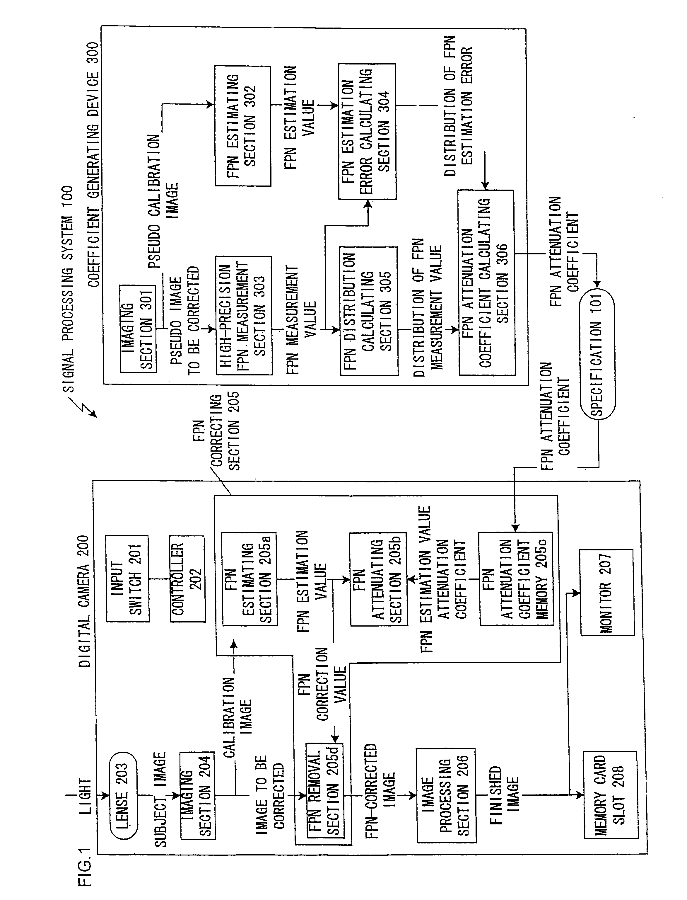
[0025]FIG. 1 is a block diagram that shows a configuration of an embodiment of a signal processing system for performing a signal processing method in accordance with a first embodiment. A signal processing system 100 includes a digital camera 200 and a coefficient generating device 300.

[0026]The digital camera 200 includes an input switch 201, a controller 202, a lens 203, an imaging section 204, a FPN correcting section 205, an image processing section 206, a monitor 207, and a memory card slot 208. Functions of the FPN correcting section 205 and the image processing section 206 are realized by an ASIC circuit.

[0027]The input switch 201 is an assembly of input members for a user to operate the digital camera 200, and includes an operation button such as a release switch.

[0028]The controller 202 controls each component of the digital camera 200 in response to an input from the input switch 201. The imaging section 204, which is a CCD for example, outputs a calibration image imaged ...

second embodiment

[0063]In the FPN correction in accordance with the first embodiment, the circuit size is slightly increased compared to the conventional methods. In the second embodiment, the increase in the circuit size is prevented. The method for improving the FPN correction accuracy without increasing the circuit size compared to the conventional methods is described.

[0064]A digital camera in accordance with the present embodiment is the digital camera 200 in FIG. 1 with a circuit includes the FPN estimating section 205a, the FPN attenuating section 205b, and the FPN attenuation coefficient memory 205c replaced with a FPN correction value calculating section 205e to be described below. Other performances of the digital camera 200 than the above is the same as those in the first embodiment.

[0065]The FPN correction value calculating section 205e sums the pixel values in each vertical line of the calibration image for the sum number of the pixels L. The sum value is divided by L′, which is a value...

third embodiment

[0073]In accordance with the first or second embodiment, an appropriate FPN correction processing is performed for most of image sensors. However, since some of the image sensors generate a high FPN in low-frequency components, making the FPN correction in accordance with the first embodiment to images that are imaged by such image sensors slightly reduces the FPN correction effects to the low-frequency components compared to the conventional methods. In the third embodiment, a FPN correction method with the above defect improved will be described.

[0074]A device in accordance with the present embodiment is the digital camera 200 in FIG. 1 with the FPN attenuating section 205b replaced with a FPN attenuating section 205β in FIG. 4. Other performances of the digital camera 200 than the FPN attenuating section 205b is the same as those in the first embodiment. Hereinafter, the performance of the FPN attenuating section 205β will be described with reference to FIG. 4.

[0075]The FPN estim...


PUM


Abstract

An estimated noise shape estimated to be included in the signal to be corrected is calculated based on a calibration signal including a noise correlating with the noise of the signal to be corrected so as to correct a noise of a signal to be corrected. A correction value of a noise shape is generated by attenuating an amplitude of the estimated noise shape, and the noise of the signal to be corrected is corrected by using the correction value of the noise shape thus generated.

Description

INCORPORATION BY REFERENCE[0001]The disclosure of the following priority application is herein incorporated by reference:[0002]Japanese Patent Application No. 2006-083237 filed Mar. 24, 2006[0003]International Patent Application No. PCT / JP2007 / 056065 filed Mar. 23, 2007BACKGROUND OF THE INVENTION[0004]1. Field of the Invention[0005]The present invention relates to a signal processing method, a signal processing system, a coefficient generating device, and a digital camera for correcting a noise included in a signal.[0006]2. Description of Related Art[0007]Generally, a FPN (Fixed Pattern Noise), vertical or horizontal streak noise, is generated on an image which is imaged with a digital camera, depending on variation in characteristics of a device that amplifies exposure-generated charge and converts it into a signal. The FPN is a noise in the same shape that is commonly generated on a plurality of images which are imaged with a same image sensor. The FPN is generated with a CCD or a...

Claims


Application Information

Patent Timeline
Patent Type & Authority Applications(United States)
IPC IPC(8): H04N5/217H04N5/365
CPCH04N1/401G06T5/002H04N17/002H04N5/365H04N25/67
Inventor UTSUGI, AKIHIKO
Owner NIKON CORP
Why Eureka
Try Eureka