Display Device
a display device and display technology, applied in the field of display devices, can solve the problem of inaccurate measurement of temperature, and achieve the effect of correcting the fluctuation of ambient light detection characteristic due to temperatur
- Summary
- Abstract
- Description
- Claims
- Application Information
AI Technical Summary
Benefits of technology
Problems solved by technology
Method used
Image
Examples
example 1
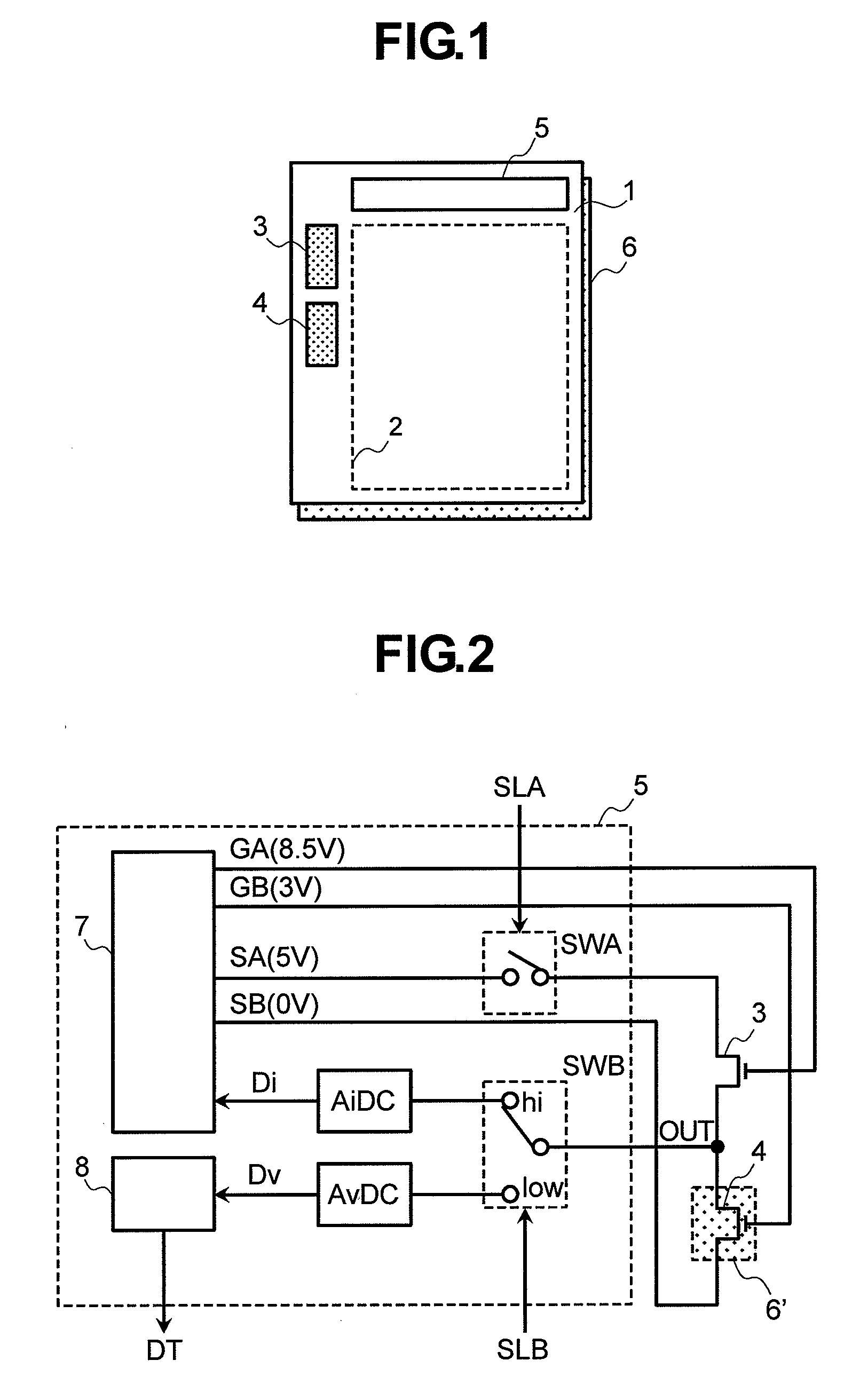
[0029]FIG. 1 shows a schematic diagram of a display device of this example. In FIG. 1, a plurality of pixels are arranged in a matrix pattern in a display area 2 of a display panel 1. In the periphery of the display area 2, a current-voltage converter 3 that linearly converts a temperature to output characteristic when temperature of the display panel 1 is detected, and a temperature detector 4 that detects temperature of the display panel 1 are disposed. Size (width W and length L) of the current-voltage converter 3 is set to be approximately the same as that of the temperature detector 4. A drive circuit 5 disposed in the periphery of the display area 2 generates a control signal for controlling each of the current-voltage converter 3 and the temperature detector 4, and a drive signal for driving the pixels in the display area 2.
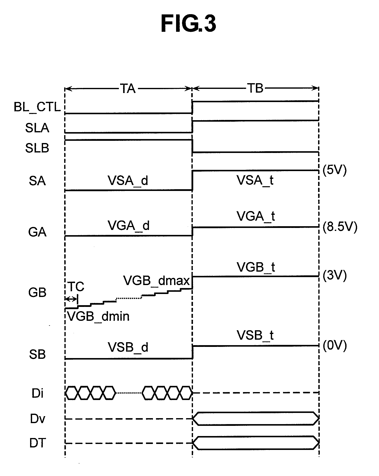
[0030]FIG. 2 is a circuit configuration diagram of the current-voltage converter 3 and the temperature detector 4 as shown in FIG. 1. In FIG. 2, the curre...
example 2
[0043]In this example, the two digital conversion circuits (AiDC and AvDC) used in the example 1 is configured by one digital conversion circuit (AviDC). Thus, since the number of circuits is decreased, the threshold voltage Vth can be detected at low cost.
[0044]FIG. 6 shows a circuit configuration diagram of the current-voltage converter 3 and the temperature detector 4 as shown in FIG. 1. In FIG. 6, a current and voltage-digital conversion circuit AviDC is formed by integrating the current-digital conversion circuit AiDC and the voltage-digital conversion circuit AvDC as shown in FIG. 2 into one unit. As a result, the changeover switch element SWB shown in FIG. 2 is unnecessary.
[0045]FIG. 7 is a timing chart for illustrating operation of the circuit of FIG. 6. Operation of the circuit is similar to operation of the circuit of FIG. 3, but different in that the current and voltage-digital conversion circuit AviDC performs digital conversion of a drain current in the period TA, and p...
example 3
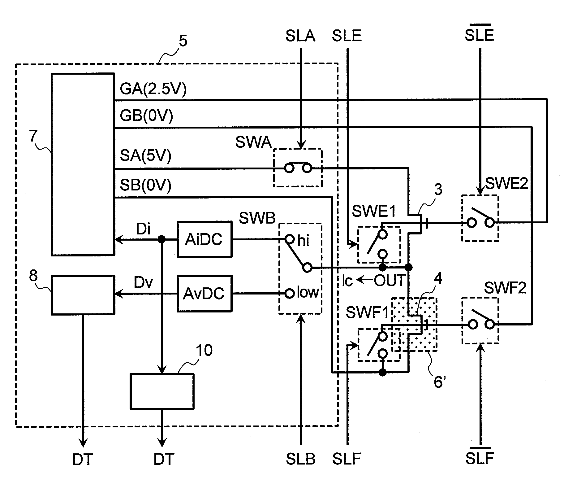
[0057]In this example, the TFT elements 3 and 4 used in the examples 1 and 2 are used to detect ambient light around a display device, and detect temperature of the display device. FIG. 11 shows a circuit configuration diagram of a TFT element 3 that detects ambient light and a TFT element 4 that detects temperature. The TFT element 3 as shown in FIG. 2 or 6 may be used to detect ambient light.
[0058]FIG. 11 is different from FIG. 2 in that an ambient light signal generator 10 is provided. When ambient light is detected, a switch element SWA is turned on. Moreover, a changeover switch element SWB is changed to a side of a current-digital conversion circuit AiDC in order to detect a signal, which is changed depending on ambient light, as a current from the TFT element 3. In this way, since an output signal Di outputted from the current-digital conversion circuit AiDC is a digital signal that varies in conjunction with ambient light, the output signal is subjected to correction process...
PUM
| Property | Measurement | Unit |
|---|---|---|
| threshold voltage | aaaaa | aaaaa |
| threshold voltage | aaaaa | aaaaa |
| threshold voltage | aaaaa | aaaaa |
Abstract
Description
Claims
Application Information
 - R&D
- Intellectual Property
- Life Sciences
- Materials
- Tech Scout
- Unparalleled Data Quality
- Higher Quality Content
- 60% Fewer Hallucinations
Browse by: Latest US Patents, China's latest patents, Technical Efficacy Thesaurus, Application Domain, Technology Topic, Popular Technical Reports.
© 2025 PatSnap. All rights reserved.Legal|Privacy policy|Modern Slavery Act Transparency Statement|Sitemap|About US| Contact US: help@patsnap.com


