Method of manufacturing an electrowetting-based variable-focus lens

a manufacturing method and electrowetting technology, applied in the field of variable lens manufacturing, can solve the problems of difficult to accurately control the position of the drop of oily liquid in the enclosure of the aqueous-liquid-filled lens, difficult to accurately control the internal pressure of the lens, and the overpressure in the lens that cannot be easily controlled accurately

Inactive Publication Date: 2009-01-22
VARIOPTIC SA
View PDF8 Cites 23 Cited by
  • Summary
  • Abstract
  • Description
  • Claims
  • Application Information

AI Technical Summary

Benefits of technology

[0006]The aim of the present invention is to provide a method of manufacturing an electrowetting-based variable-focus lens that allows simple and precise positioning of the liquids contained in the lens, and also an electrowetting-based variable-focus lens obtained by such a method.
[0007]Another object of the present invention is to allow the internal pressure of the lens when assembling the lens to be fixed in a simple and precise manner.

Problems solved by technology

With such a method of assembly, it may be difficult for the position of the drop of the oily liquid in the enclosure of the aqueous-liquid-filled lens to be accurately controlled.
Furthermore, when closing off the enclosure of the lens, it may be difficult for the internal pressure of the lens to be accurately controlled.
At the end of the method of assembling the lens, there is therefore an overpressure in the lens that cannot be easily controlled accurately.

Method used


Image

  • Method of manufacturing an electrowetting-based variable-focus lens
  • Method of manufacturing an electrowetting-based variable-focus lens

Examples


Embodiment Construction

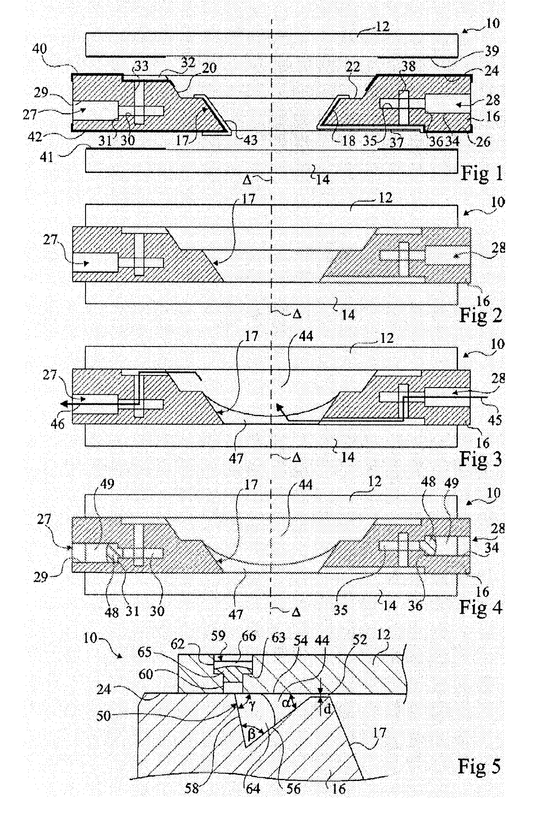
[0027]For the sake of clarity, identical elements have been denoted by identical references in the various figures.

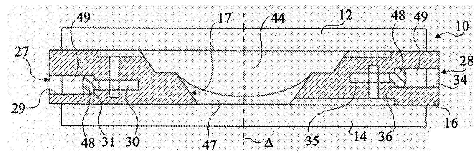
[0028]FIG. 1 is a sectional exploded view of a first exemplary embodiment of a variable-focus lens 10 according to the invention, comprising upper and lower circular transparent plates 12 and 14 of axis Δ and an annular ring 16 of axis A. The ring 16 has a central opening 17 which is bounded by a lower truncated-cone-shaped wall 18 (in other words a conical frustum) and an upper truncated-cone-shaped wall 20 that are separated by a shoulder 22. The ring 16 further comprises, on its upper surface, a planar face 24 on which the upper plate 12 is intended to bear, in order to form the topside of an enclosure. Similarly, the ring 16 comprises, on its lower face, a planar bearing surface 26 on which the lower plate 14 is intended to bear, in order to form the underside of the enclosure. The plates 12 and 14 and the ring 16 may be made of rigid insulating materials, for examp...


PUM


Abstract

The present invention relates to a method of manufacturing an electrowetting-based variable-focus lens, comprising: (a) providing an enclosure having a cavity (17) and at least one channel (27, 28; 59) communicating at one end with the cavity and at the other end emerging at the exterior surface of the lens; (b) filling the cavity with first and second liquids (44, 47) that are immiscible and of different refractive indices via the channel; and (c) hermetically scaling the channel.

Description

FIELD OF THE INVENTION[0001]The present invention relates to a method of manufacturing a variable-focus lens and more particularly to a method of manufacturing a lens involving the deformation of a drop of liquid by electrowetting effects. The present invention also relates to an electrowetting-based variable-focus lens obtained by such a method.SUMMARY OF THE PRIOR ART[0002]A variable-focus lens comprises an enclosure, generally bounded by two transparent parallel plates, which contains at least two immiscible liquids of different refractive indices. In general, one of the liquids is an aqueous liquid and the other liquid is an oily liquid. The interface between the two liquids defines a movable refractive interface through which the light rays received by the lens pass. The lens comprises means for deforming the movable dioptric interface by electrowetting effects, thus making it possible to modify the optical power of the lens.[0003]Such electrowetting-based variable-focus lenses...

Claims


Application Information

Patent Timeline
Patent Type & Authority Applications(United States)
IPC IPC(8): G02B3/14
CPCG02B26/005G02B3/14
Inventor BERGE, BRUNOPESEUX, JEROMEBOUTAUD, BERTRANDCRAEN, PIERRE
Owner VARIOPTIC SA
Why Eureka
Try Eureka