Metal/Fiber Laminate and Fabrication Using A Porous Metal/Fiber Preform

Active Publication Date: 2009-01-22
NASA
View PDF29 Cites 11 Cited by
  • Summary
  • Abstract
  • Description
  • Claims
  • Application Information

AI Technical Summary

Benefits of technology

[0008]Another object of the present invention is to provide a metal/composite laminate having improved bond strength.
[0009]Still an

Problems solved by technology

However, both autoclave and press molding techniques require complex tooling and are limited in size/shape owing to the size limitations of autoclave or pr

Method used


Image

  • Metal/Fiber Laminate and Fabrication Using A Porous Metal/Fiber Preform
  • Metal/Fiber Laminate and Fabrication Using A Porous Metal/Fiber Preform
  • Metal/Fiber Laminate and Fabrication Using A Porous Metal/Fiber Preform

Examples


Embodiment Construction

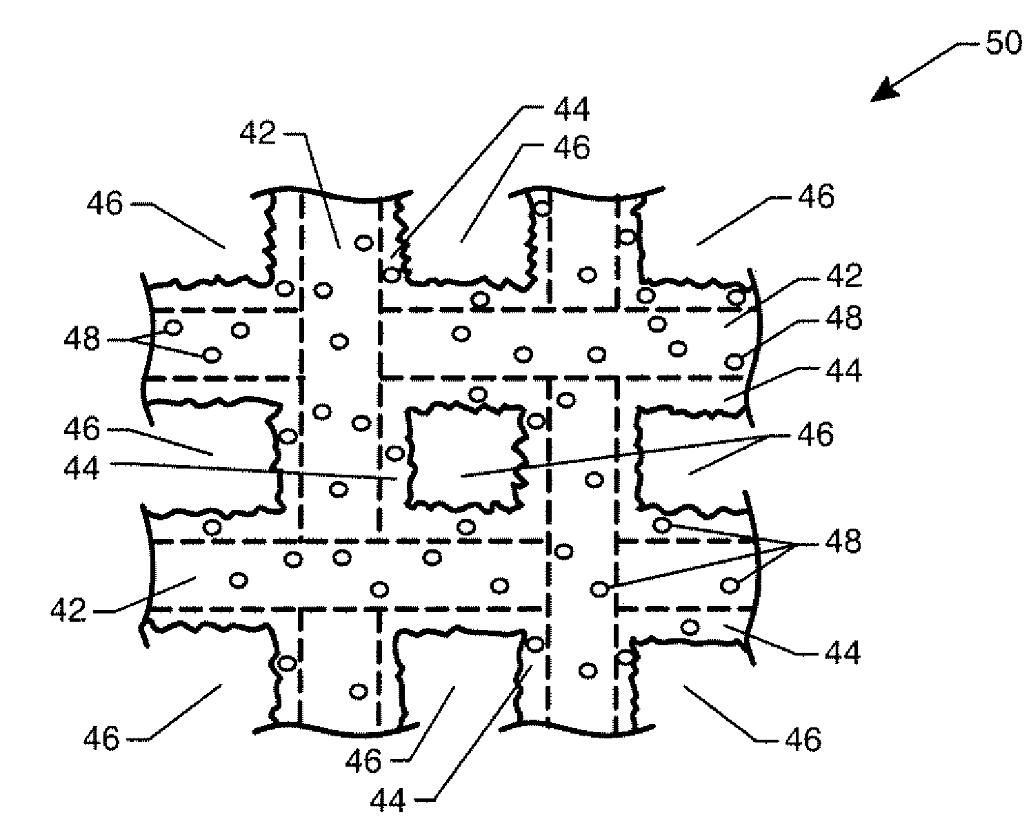
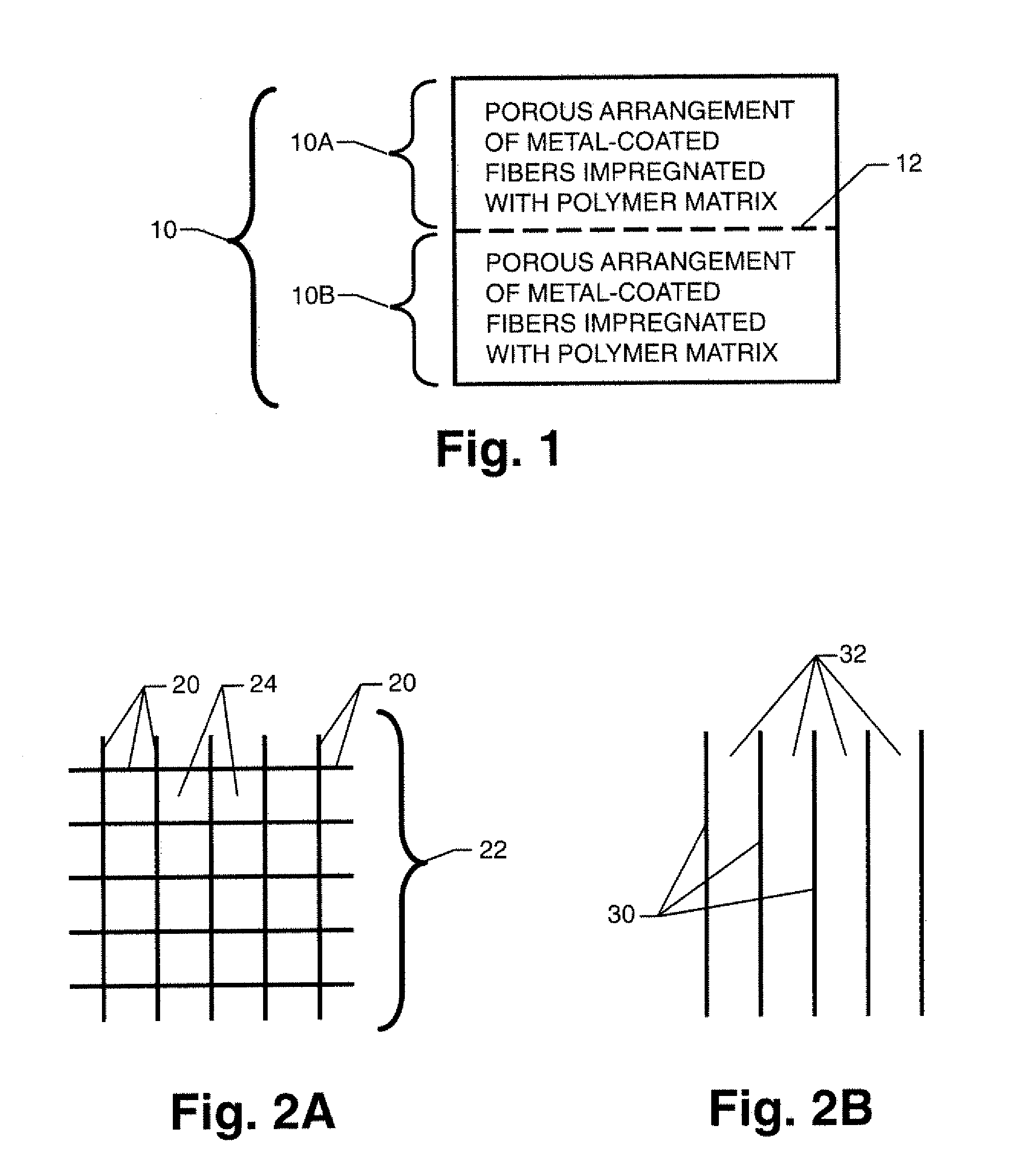
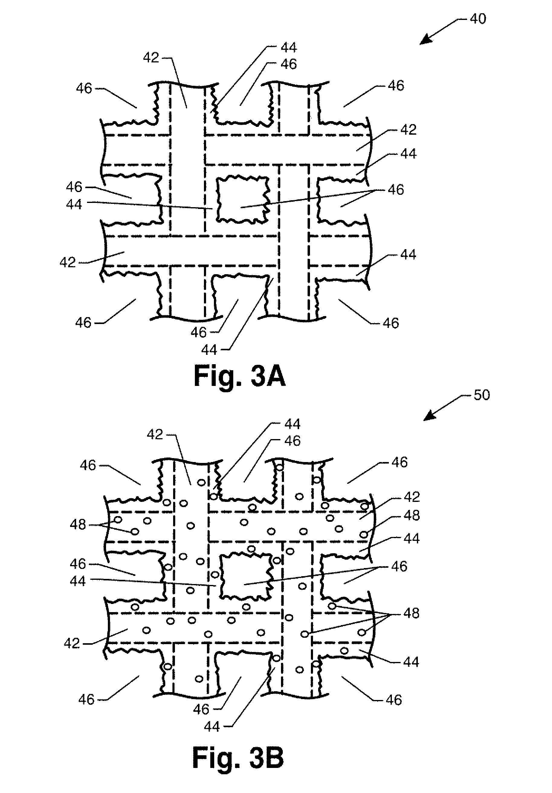
[0021]Referring now to the drawings and more particularly to FIG. 1, a metal / fiber laminate in accordance with the present invention is shown schematically and is referenced generally by numeral 10. Although laminate 10 is illustrated with two layers 10A and 10B, it is to be understood that more layers can be provided without departing from the present invention. There are even some applications that might only require one such layer as will be explained further below. It is further to be understood that layers 10A / 10B and the resulting laminate 10 can be planar or complex in shape without departing from the scope of the present invention.

[0022]In general, each layer 10A and 10B of laminate 10 is a porous arrangement of metal-coated fibers with the porosity of such arrangement being permeated with a polymer matrix. As would be understood in the art, the term “fibers” as used herein includes individual fibers as well as multi-fiber tows. As will be explained further below, the polyme...


PUM

PropertyMeasurementUnit
Pressureaaaaaaaaaa
Electrical conductoraaaaaaaaaa

Abstract

A metal/fiber laminate has a plurality of adjacent layers. Each layer is porous and includes an arrangement of fibers. At least one of the layers has its fibers coated with a metal. A polymer matrix permeates each such arrangement.

Description

[0001]Pursuant to 35 U.S.C. §119, the benefit of priority from provisional application 60 / 941,793, with a filing date of Jun. 4, 2007, is claimed for this non-provisional application.ORIGIN OF THE INVENTION[0002]The invention was made in part by employees of the United States Government and may be manufactured and used by or for the Government of the United States of America for governmental purposes without the payment of any royalties thereon or therefor.FIELD OF THE INVENTION[0003]This invention relates to metal / composite laminates and the fabrication thereof. More specifically, the invention is a metal / fiber laminate and a fabrication method for the laminate that uses a porous metal / fiber preform.DESCRIPTION OF THE RELATED ART[0004]Metal / composite hybrid laminates provide a combination of structural and functional properties for a variety of applications to include aerospace structures. When comparing a structure made from a metal / composite hybrid laminate with one made from jus...

Claims


Application Information

Patent Timeline
IPC IPC(8): B32B5/26
CPCB32B5/26B32B19/06B32B27/02Y10T428/2944Y10T156/10Y10T428/294B32B27/38Y10T428/249951Y10T428/249962Y10T442/2098Y10T442/2139
Inventor HALES, STEPHEN J.ALEXA, JOEL A.JENSEN, BRIAN J.CANO, ROBERTO J.WEISER, ERIK S.
Owner NASA
Why Eureka
Try Eureka