
Endoscopic Instrument

a technology of endoscopic instruments and hollow shanks, applied in the field of endoscopic instruments, can solve the problems of inconvenient endoscopic application, inconvenient use of endoscopic instruments, and inability to adapt to endoscopic applications

Active Publication Date: 2009-01-22
RICHARD WOLF GMBH
View PDF19 Cites 59 Cited by
  • Summary
  • Abstract
  • Description
  • Claims
  • Application Information

AI Technical Summary

Benefits of technology

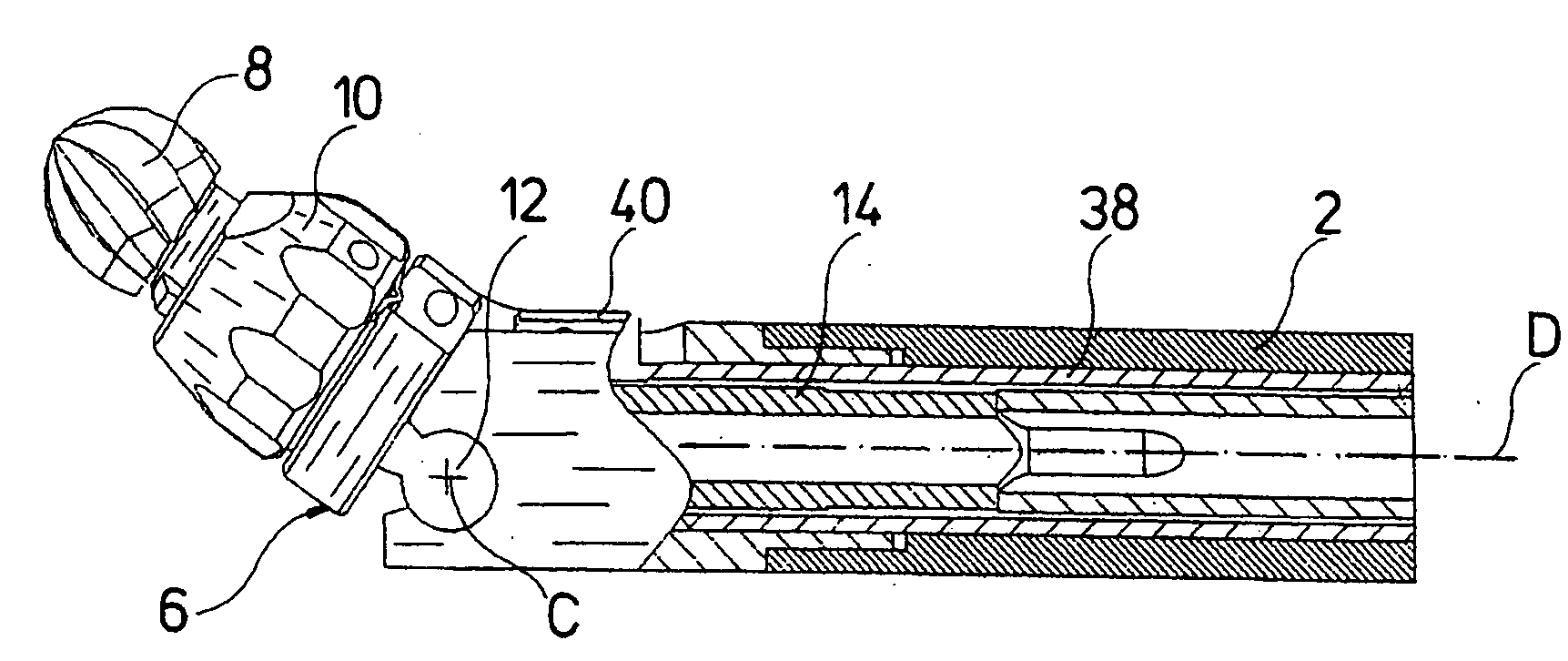
[0012]Advantageously, a universal joint is provided in order to be able to actively connect the tool to the drive shaft guided in the hollow shank, also in this position, which is angled with respect to the hollow shank. The universal joint couples the tool in movement to the drive shaft in a direct or indirect manner. The universal joint permits the tool to be angled with respect to the drive shaft led into the hollow shank. Thus, the drive shaft and the tool may be arranged in an axially equal manner in a first position, while the rotation axis of the tool in a second position may be angled with respect to the rotation axis of the drive shaft. The universal joint, on account of its great stiffness in the rotation direction, permits the transmission of relatively large torques in both positions, even at large rotation speeds, which permits the removal of hard material or tissue, in particular the removal of bone tissue.
[0015]In order to be able to move the tool into a position which is angled with respect to the distal end of the hollow shank, the head part is usefully coupled in movement via a joint part to an actuation rod, which is movable in the hollow shank in the axial direction. The joint part is preferably articulated on the distal end of the actuation rod and on the head part, wherein on the head part it is usefully also displaceable in a direction transversely to the longitudinal axis of the head part. With this design, having only one device consisting of the actuation rod and the joint part, it is advantageously possible by displacing the actuation rod in the axial direction of the hollow shank, to pivot the head part with the tool arranged therein, into a position which is angled to the distal end of the hollow shank, as well as back into a position which is flush with the hollow shank.

Problems solved by technology

Particularly with narrow access channels these instruments come up against limitations, when the tissue to be removed is located laterally of an access axis defined by the access channel.
These instruments with a rigidly angled hollow shank end and tool, however, are not suitable for endoscopic application, since they may not be led through a straight working channel of an endoscope.
However, the bending radius of the hollow shanks with these instruments is relatively large, so that the tools arranged at the distal end of the hollow shank may lie outside the scope of endoscopic optics, and an operative operation carried out with these instruments must, as a rule, be observed with additional optical means.
A further disadvantage of these instruments lies in the fact that on application of a tool operated in a rotating manner, a drive shaft led through the hollow shank must likewise be bendable, i.e., must be designed in a flexible manner, whereby only relatively small torques at simultaneously low rotation speeds may be transmitted with these drive shafts.
For this reason, these instruments are not suitable for removal of hard tissue, such as bone material.

Method used


Image

  • Endoscopic Instrument
  • Endoscopic Instrument
  • Endoscopic Instrument

Examples


Embodiment Construction

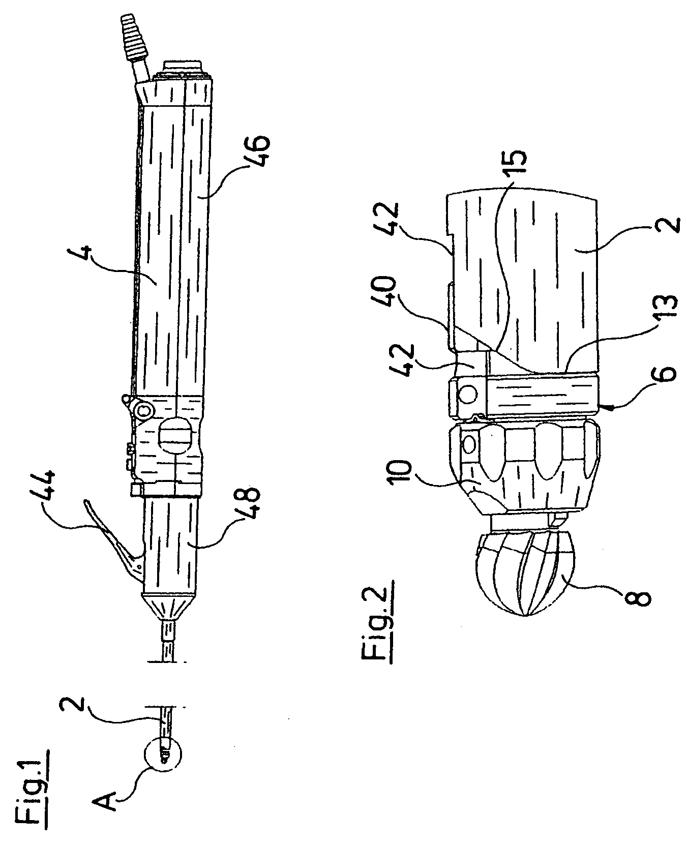
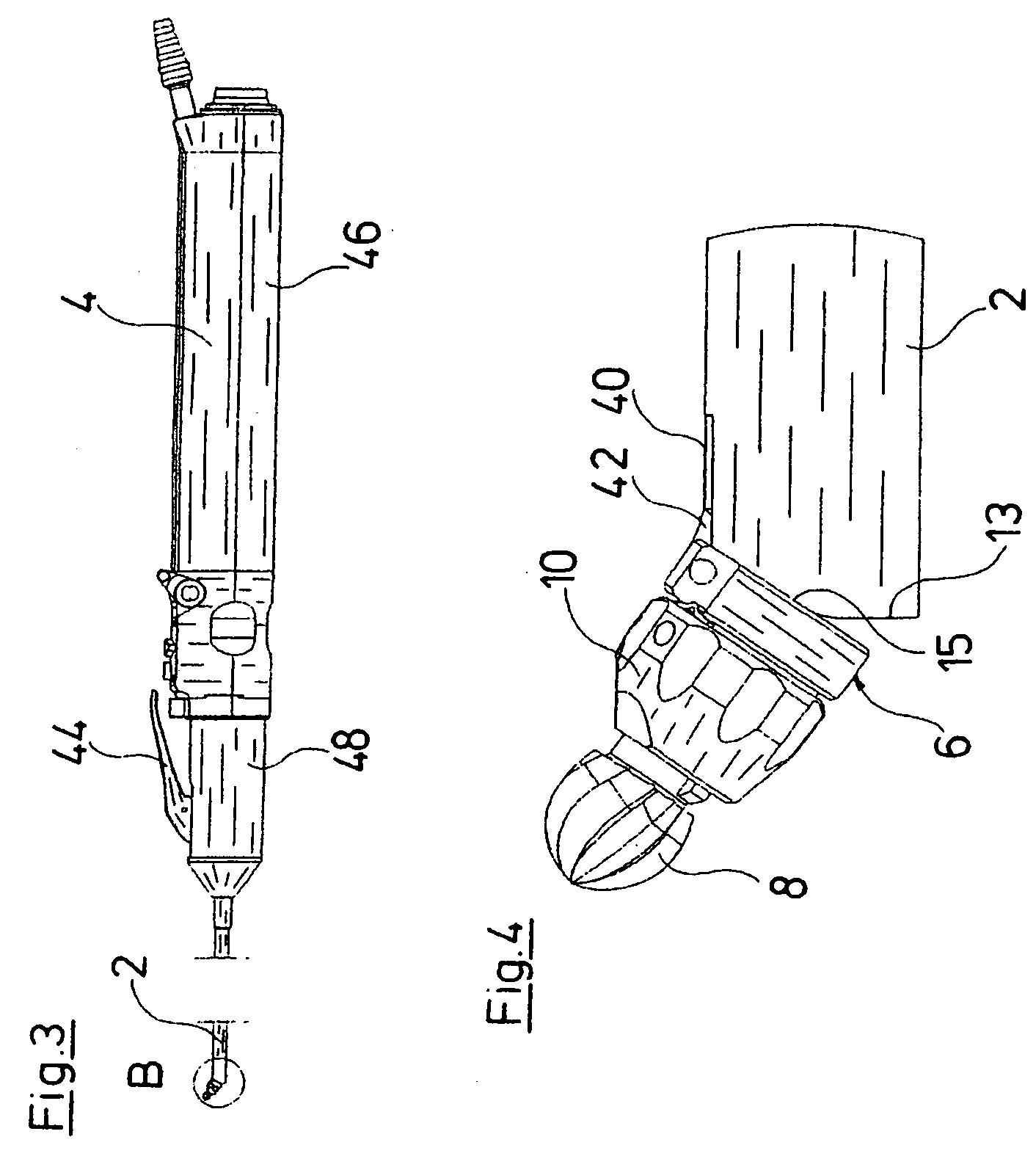
[0027]The endoscopic instrument represented in the figures comprises a rigid hollow shank 2. This hollow shank 2 is arranged on the distal end of a grip part 4. The hollow shank 2 forms the part of the endoscopic instrument via which the working channel of an endoscope, which is not shown, is introduced into the inside of a body. A head part 6 is arranged outside the distal end of the hollow shank 2, and a tool in the form of a miller head 8 is mounted in this head part. The head part 6 at its distal end comprises a closure element 10 with which the miller head 8 may be releasably fastened in the head part 6. For this, a clamping device is provided in the closure element 10, with which device the miller head 8 may be firmly clamped with a non-positive fit.

[0028]The head part 6 is pivotably mounted about an axis C on a joint 12 at the distal end of the hollow shank 2 (see FIG. 7). The axis C extends normally to a longitudinal axis D of the hollow shank 2. The pivotability of the head...


PUM


Abstract

An endoscopic instrument includes a rigid hollow shank (2) and a tool (8) at the distal instrument end. The tool (8) is driven in rotation via a drive shaft (14), which is guided within the hollow shank (2). At the distal end of the hollow shank (2), the tool (8) projects out of the hollow shank (2), where it may be angled with respect to the distal end of the hollow shank (2).

Description

BACKGROUND OF THE INVENTION[0001]The invention relates to an endoscopic instrument for removing material, tissue and the like, and having a rigid hollow shank and a tool at the distal instrument end, the tool being driven in rotation via a drive shaft led into the hollow shank.[0002]Instruments are known from the field of medicine, which may be introduced into body cavities via natural or artificially created access channels, in order to remove tissue there with these instruments. Such instruments usually comprise a hollow shank, which may be introduced through the access channel into the body cavity, at whose distal end a rotating tool for removing tissue is arranged in the extension of the hollow shank. Particularly with narrow access channels these instruments come up against limitations, when the tissue to be removed is located laterally of an access axis defined by the access channel.[0003]Instruments are known in which the distal end region, with a tool located thereon, is des...

Claims


Application Information

Patent Timeline
IPC IPC(8): A61B1/00A61B17/00A61B17/26
CPCA61B17/1624A61B17/1633A61B2017/320032A61B2017/2927A61B17/32002
Inventor KORNER, EBERHARDSCHMID, FRANCPRESTEL, STEPHAN
Owner RICHARD WOLF GMBH
Learn More