
Remaining-Amount Estimation Device and Method For Secondary Battery

a secondary battery and remaining amount technology, applied in measurement devices, instruments, transportation and packaging, etc., can solve the problems of reducing capacity, affecting the accuracy of estimation, so as to avoid excessive charging and excessive discharging, the effect of high accuracy

Active Publication Date: 2009-01-22
TOYOTA JIDOSHA KK
View PDF10 Cites 23 Cited by
  • Summary
  • Abstract
  • Description
  • Claims
  • Application Information

AI Technical Summary

Benefits of technology

[0011]The present invention is made to solve the above-described problems. An object of the present invention is to provide a remaining-amount estimation device and method for the secondary battery for estimating the remaining amount of the secondary battery with high accuracy while avoiding excessive charging and excessive discharging with more stability.
[0014]Therefore, in the case of being in the range in proximity to excessive charging or excessive discharging, the remaining-amount estimation value can be calculated so as to indicate the safe side (further excessive charging side or further excessive discharging side) value for the secondary battery in the charge / discharge control. In the range other than the above-mentioned range, it is possible to enhance the followability to the second estimation value to improve the estimation accuracy of the remaining-amount estimation value.
[0023]Consequently, in the case where the second estimation value is in the range in proximity to excessive charging and the input current to the secondary battery is large, and, in the case where the second estimation value is in the range in proximity to excessive discharging and the output current from the secondary battery is large, it is possible to enhance the followability to the second estimation value to improve the estimation accuracy of the remaining-amount estimation value.
[0034]According to the present invention, a remaining-amount estimation device and method for the secondary battery can be achieved for estimating the remaining amount of the secondary battery with high accuracy while avoiding excessive charging and excessive discharging with more stability.

Problems solved by technology

In this current integration scheme, for example, in the case where the battery is not fully charged, the improvement in the estimation accuracy is limited due to the reasons including the effects of the error resulting from cancellation of the least significant bit in the processing device (CPU) performing the current integration, capacity decrease caused by self-discharge, and the like, or high dependence on the current sensor accuracy.
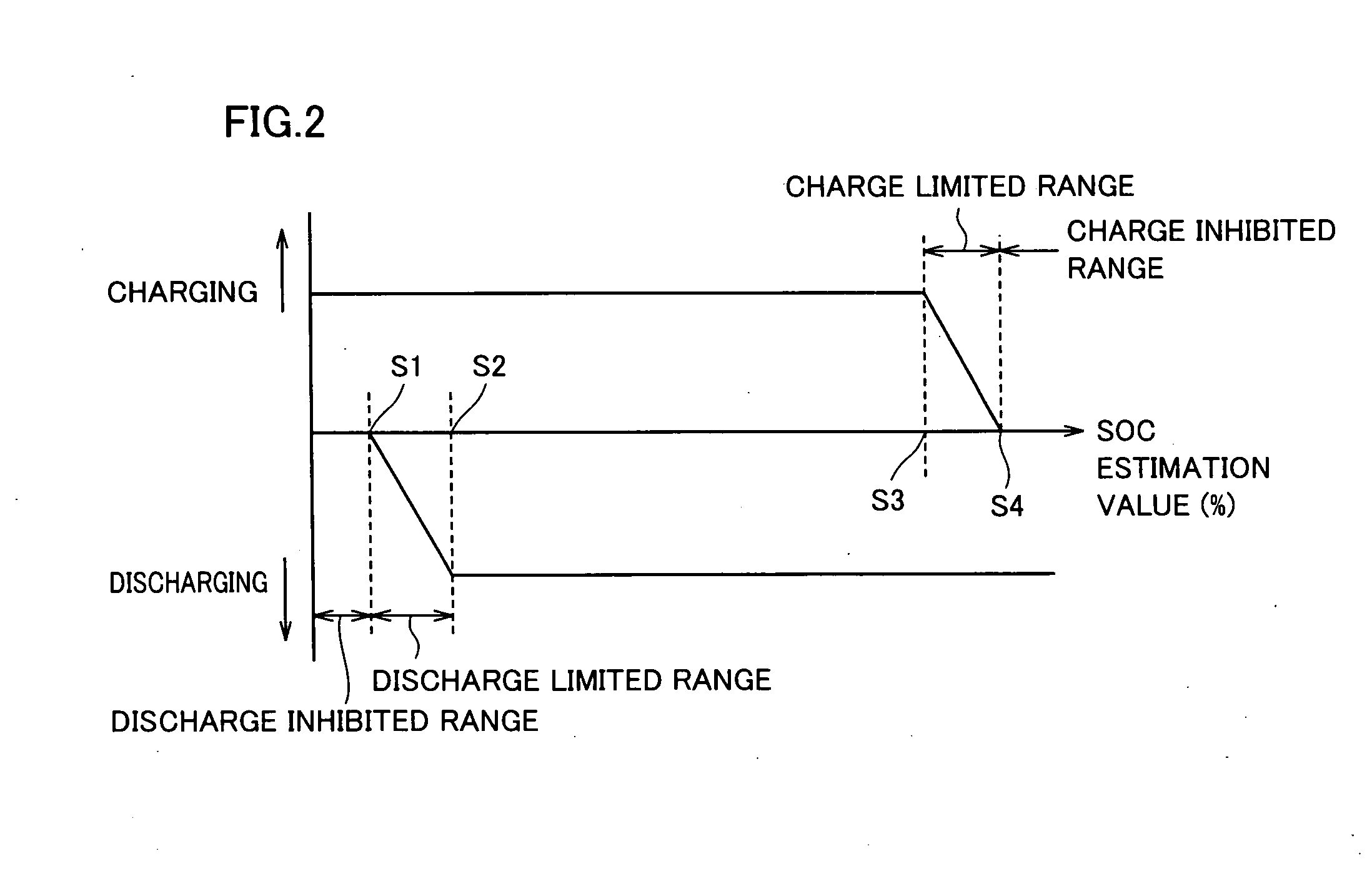
In other words, while charging is limited or inhibited in the case of exceeding the management upper limit value, discharging is limited or inhibited in the case of falling below the management lower limit value.
In view of avoiding the excessive charging of the secondary battery, the above-described correction produces the opposite effect, which increases the possibility of excessive charging on the contrary.
Similarly, even if the estimated SOC based on the current integrated value (for example, 15%) is in close proximity to the management lower limit value (for example, 10%) as compare to the estimated SOC based on the electromotive voltage (for example, 20%), the estimated SOC based on the current integrated value is largely corrected further upward, that is, to be away from the management lower limit value, which increases the possibility of excessive discharging on the contrary.
Accordingly, in the case where the remaining amount is in proximity to the management upper limit value, the generation of large charging current may cause excessive charging.
In the case where the remaining amount is in proximity to the management lower limit value, the generation of large discharging current may cause excessive discharging.

Method used


Image

  • Remaining-Amount Estimation Device and Method For Secondary Battery
  • Remaining-Amount Estimation Device and Method For Secondary Battery
  • Remaining-Amount Estimation Device and Method For Secondary Battery

Examples


first embodiment

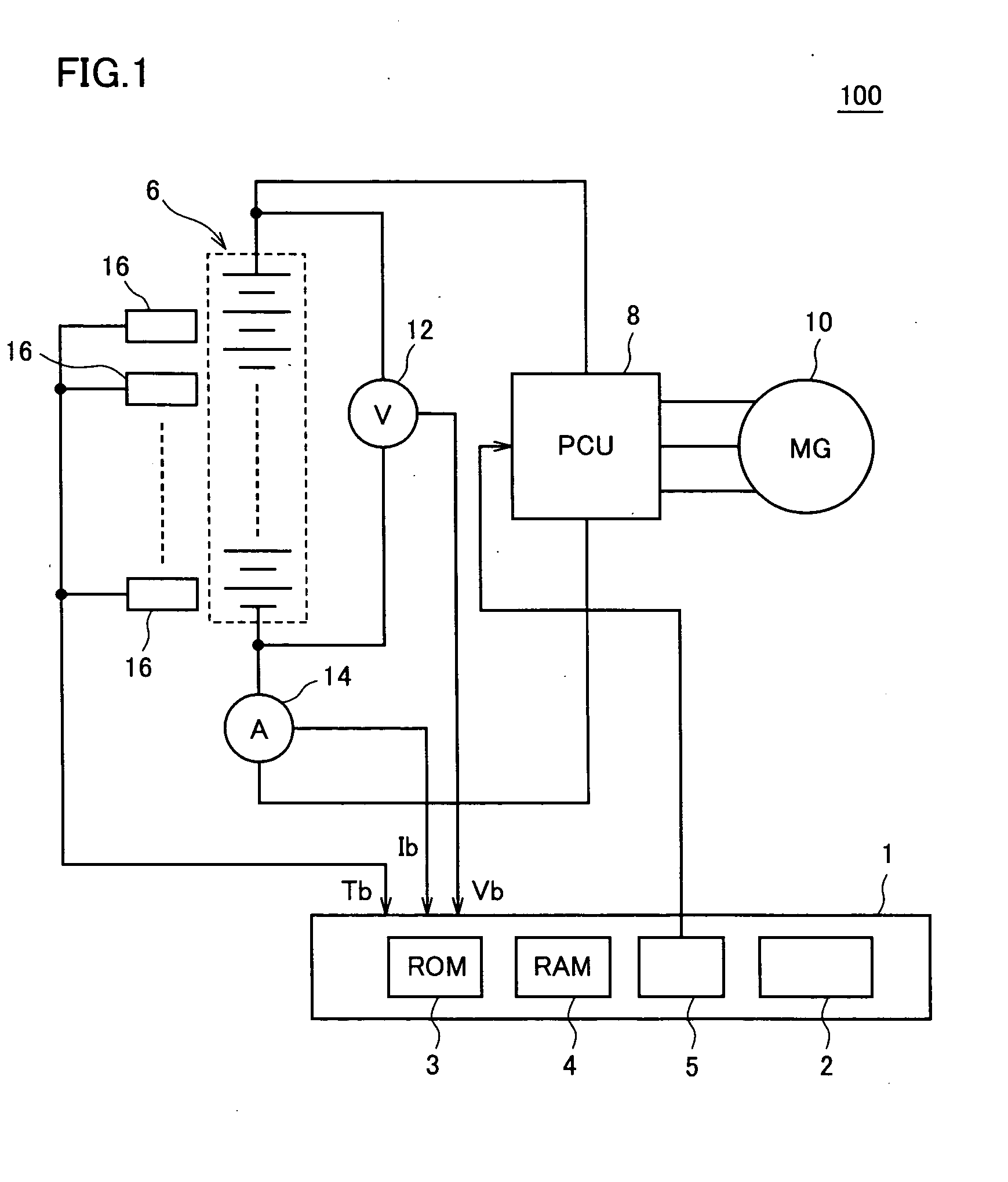
[0048]Referring to FIG. 1, a vehicle 100 includes a secondary battery 6, a PCU (Power Control Unit) 8, a motor generator (MG) 10, an ECU 1, a voltage measurement unit 12, a current measurement unit 14, and a temperature measurement unit 16. Vehicle 100 is a hybrid vehicle which runs by at least one of the driving force from motor generator 10 and the driving force from the engine which is not shown. Instead of a hybrid vehicle, the vehicle may be a fuel vehicle incorporating a fuel cell or an electric vehicle which runs only using the driving force from the motor generator.

[0049]Secondary battery 6 is a battery set having a configuration in which a plurality of battery modules each consisting of a plurality of integrated battery cells are connected in series and, by way of example, includes a lithium ion battery, a nickel metal hydride battery, and the like. Secondary battery 6 is configured to be charged and discharged by means of PCU 8.

[0050]PCU 8 converts DC (Direct Current) powe...

second embodiment

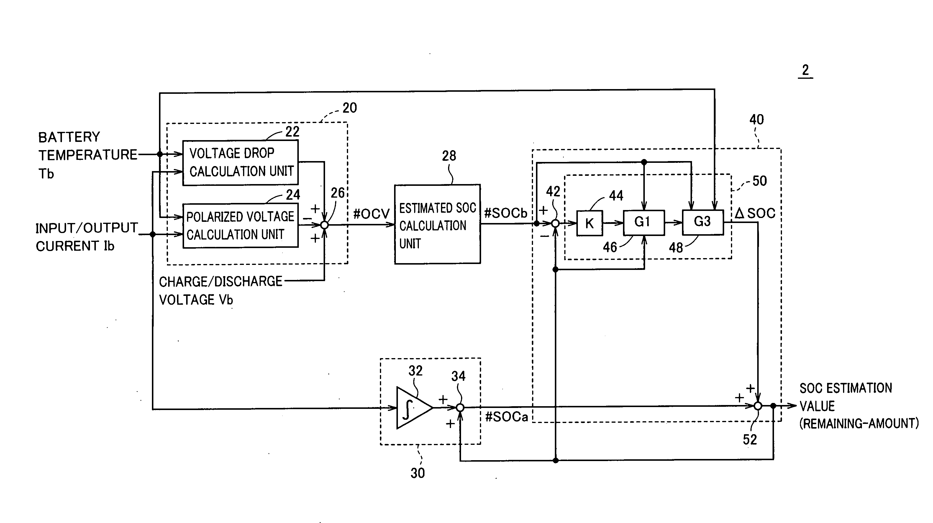
[0117]In the above-described first embodiment of the present invention, the configuration in which correction value ΔSOC is calculated by the correction gains selected based on the SOC estimation value (last calculated value), the estimated SOC (#SOCb) and the battery temperature, respectively, has been described. In the second embodiment of the present invention, the configuration in which correction value ΔSOC is calculated by the correction gains selected based on the input / output current, the estimated SOC (#SOCb) and the battery temperature, respectively, will be described.

[0118]Referring to FIG. 9, an SOC estimation unit 2A according to the second embodiment of the present invention is equivalent to SOC estimation unit 2 according to the first embodiment of the present invention shown in FIG. 3 except that it has an SOC calculation unit 40A in place of SOC calculation unit 40, to which SOC calculation unit 40A is equivalent except that it has a correction value calculation uni...

third embodiment

[0144]In the above-described first and second embodiments of the present invention, the configuration in which the correction value is calculated by the correction gains selected based on the SOC estimation value (last calculated value), the estimated SOC (#SOCb) and the battery temperature, and the configuration in which the correction value is calculated by the correction gains selected based on the input / output current, the estimated SOC (#SOCb) and the battery temperature have been described, respectively. In the third embodiment of the present invention, the configuration in which the correction value is calculated by all the above correction gains will be described.

[0145]Referring to FIG. 12, an SOC estimation unit 2B according to the third embodiment of the present invention is equivalent to SOC estimation unit 2 according to the first embodiment of the present invention shown in FIG. 3 except that it has an SOC calculation unit 40B in place of SOC calculation unit 40, to whi...


PUM


Abstract

An SOC-estimation-value-depending gain selection unit multiplies the deviation of an SOC estimation value (last calculated value) relative to an estimated SOC by a correction gain G1 to calculate a correction value. The SOC-estimation-value-depending gain selection unit selects a relatively small correction gain G1 when the SOC estimation value lies in the range in proximity to excessive charging and the SOC estimation value is corrected to a smaller value (toward the SOC control center), and when the SOC estimation value lies in the range in proximity to excessive discharging and the SOC estimation value is corrected to a larger value (toward the SOC control center). Thus, the correction is performed so as to indicate the safe side value for the secondary battery in charge / discharge control when the SOC estimation value is in proximity to excessive charging or excessive discharging.

Description

TECHNICAL FIELD[0001]The present invention relates to a device and method for estimating a remaining amount of a chargeable secondary battery, and particularly to a technique for avoiding excessive charging and excessive discharging of the secondary battery with more stability.BACKGROUND ART[0002]The secondary battery, which is used in various fields, requires the appropriate charge / discharge control for the efficient operation thereof This requires the remaining amount of the secondary battery (State of Charge; hereinafter simply referred to as an SOC) to be estimated with high accuracy.[0003]Conventionally, a so-called current integration scheme is known, in which the input / output current of the secondary battery is integrated to estimate the SOC. In this current integration scheme, for example, in the case where the battery is not fully charged, the improvement in the estimation accuracy is limited due to the reasons including the effects of the error resulting from cancellation ...

Claims


Application Information

Patent Timeline
IPC IPC(8): G01R31/36
CPCG01R31/3651G01R31/3624G01R31/367G01R31/3842G01R31/36
Inventor SUZUKI, YUSUKE
Owner TOYOTA JIDOSHA KK
Learn More