
Method and a System for Cable or Subscriber Loop Investigation Performing Loop Topology Identification

a topology identification and cable or subscriber technology, applied in the direction of noise figure or signal-to-noise ratio measurement, line-transmission details, instruments, etc., can solve the problems of multi-dimensional optimization, unsatisfactory existing documentation, and well-designed filters optimized for a cable length of about 1 km, so as to facilitate transmission line or subscriber loop investigation, facilitate maintenance, and facilitate troubleshooting

Active Publication Date: 2009-01-22
TELEFON AB LM ERICSSON (PUBL)
View PDF6 Cites 19 Cited by
  • Summary
  • Abstract
  • Description
  • Claims
  • Application Information

AI Technical Summary

Benefits of technology

[0010]What is needed is therefore a method as initially referred to which facilitates transmission line or subscriber loop investigation. A method is also needed which facilitates maintenance. Further yet a method is needed which facilitates trouble-shooting in transmission lines or in the subscriber loop. A method is also needed which facilitates introduction of xDSL in that a method is provided for investigation of cables to establish whether they can be used for DSL or not. Particularly a method is needed through which investigation of multi-segment cables is facilitated. Even more particularly a method is needed through which cables can be investigated in a more reliable, faster, easier and cheaper manner, particularly without requiring any particular prior knowledge, for example as to the number of cable segments, lengths of the segments etc.
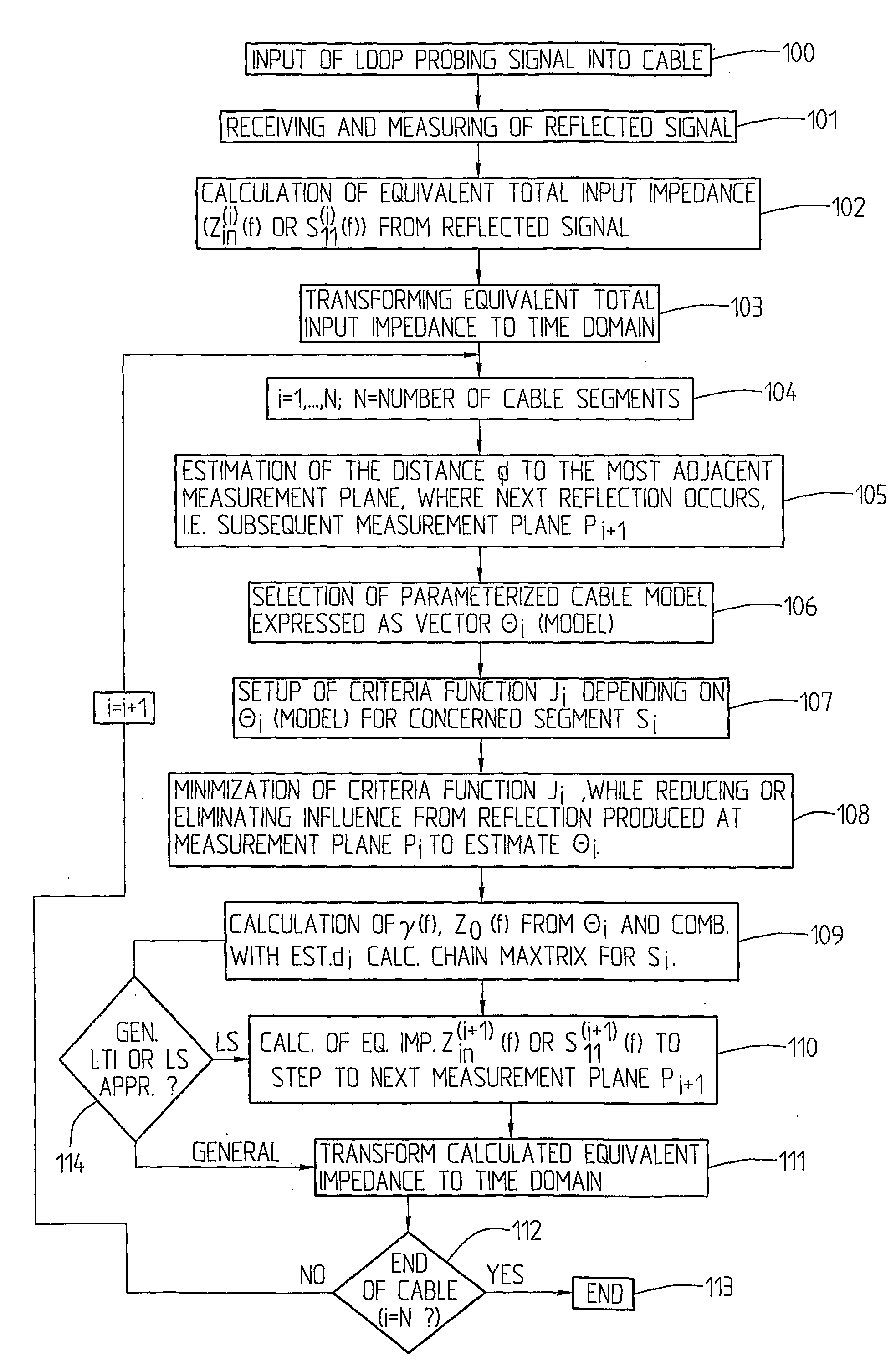
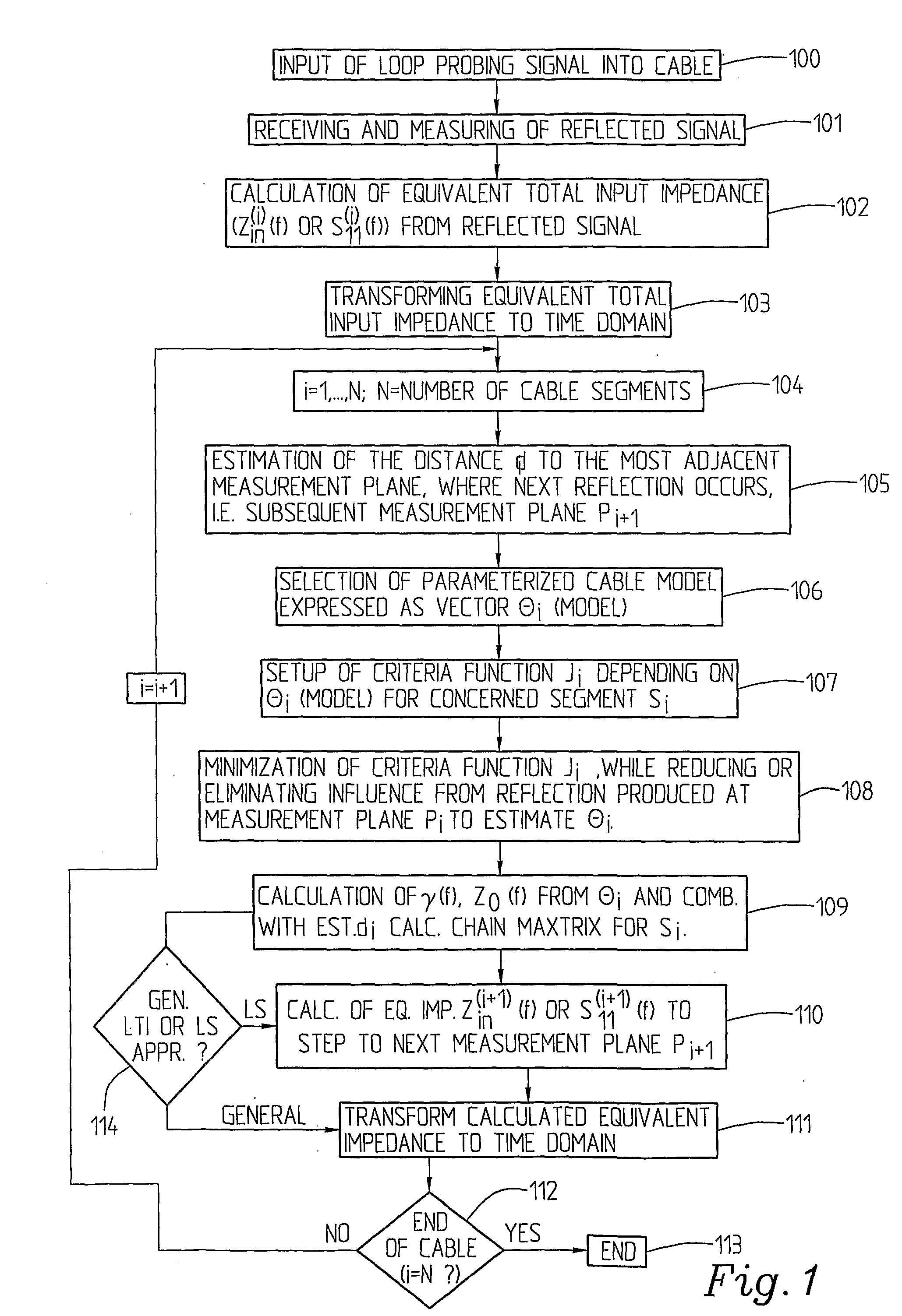
[0015]In specific implementations thereof it may comprise the step of; using a Hilbert transform to reduce the number of unknown parameters hence providing a vector θ with a reduced number of unknown parameters, e.g. θ=[roc,ac,Lc∞,Cconst] although it is not necessary for the inventive concept to use a Hilbert transform. The minimizing step particularly comprises; performing an optimization using an optimization algorithm to estimate at least some of the unknown primary parameters and allowing calculation or estimation of the unknown secondary parameters comprising the respective characteristic impedance and the propagation constant or velocity of the respective cable segment. Even more particularly the optimization step comprises, based on a criteria function Ji defined in the time or the frequency domain, for the respective segment si; transforming the used frequency domain criteria function to time domain; using time indices indicating the time interval corresponding to the respective cable segment si, i=1, . . . , N; minimizing the respective criteria function Ji in each iterative step, i.e. for each consecutive cable segment si.

Problems solved by technology

However, in order to be able to model a multi-segment cable, a multi-dimensional optimization is required, which is very difficult without a priori knowledge, for example concerning the number of cable segments and the length of each segment, which normally is not available.
This means that existing documentation might not at all be adequate.
This may cause problems when implementing the TDR technique, since an ADSL transceiver actually is not designed for SELT.
However, as an example, a well-designed filter optimized for a cable length of about 1 km will not perform well for a cable length of 4 km and vice versa.
However, the applied filters have to have band-pass characteristic which makes the sign of the TDR signal difficult to analyze, which is of significant importance e.g. when detecting bridge-taps and type of far-end termination.
However, since an enormous amount of different kinds of cables exist in the telecommunication networks, the database must be very large.
Even more serious is the problem that some of the used cables are entirely unknown to the operators.
Furthermore temperature variations and degradations over time make the characteristic of the cables change with time.
This makes establishment of whether a cable can be used for DSL or not almost impossible and it also makes maintenance difficult as well as trouble-shooting.

Method used


Image

  • Method and a System for Cable or Subscriber Loop Investigation Performing Loop Topology Identification
  • Method and a System for Cable or Subscriber Loop Investigation Performing Loop Topology Identification
  • Method and a System for Cable or Subscriber Loop Investigation Performing Loop Topology Identification

Examples


Embodiment Construction

[0028]The concept of the present invention is based on successive modelling and estimation. The characteristics of each cable segment is iteratively estimated and a loop topology identification can be carried out through splitting of the task into subtasks which can be solved more easily.

[0029]The loop topology identification, in the following denoted LTI, can be broken down into the following identification / estimation tasks assuming that no load coils are present. The problems associated with load coils and the detection of such depends on the used measurement equipment, where normal xDSL modems may not have access to the required low frequencies needed for the detection of such impairments. The present invention is general and independent of access to low frequencies, and can of course be easily combined with a load coil detector. Hence the number of cable segments needs to be identified as well as the length of each segment. Furthermore the kind of the segment, for example a seri...


PUM


Abstract

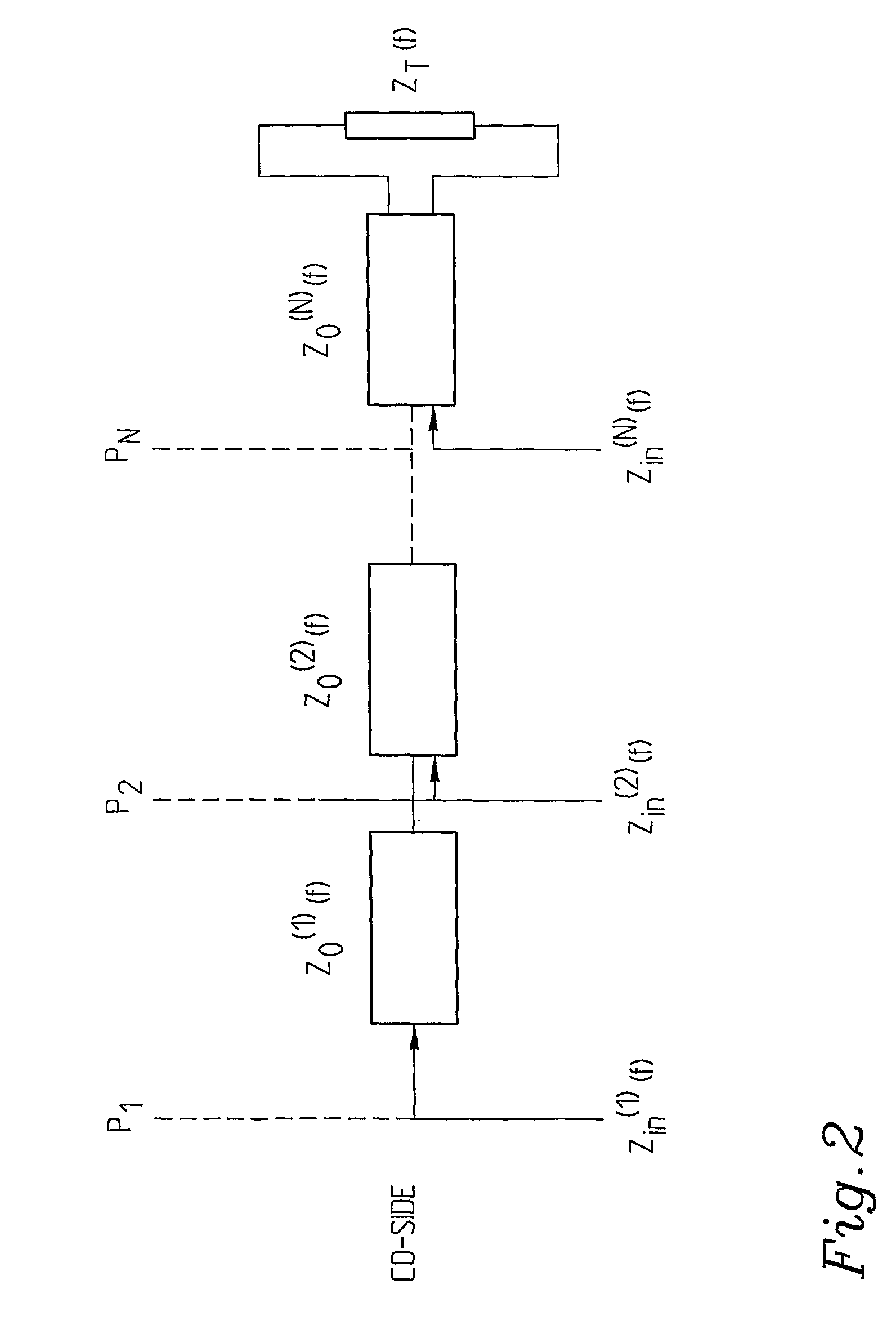
A system and method for using loop topology identification to investigate a transmission line having a plurality of cable segments. At a measurement plane for each segment, a probing signal is transmitted into the cable. A reflected signal is detected, and an equivalent total input impedance is calculated. The system iteratively calculates the distance between the measurement planes as well as the length, characteristic impedance, and the propagation constant of each segment. A model is used to calculate the respective equivalent input impedance of each segment using the calculated characteristic impedance, propagation constant, and length of the preceding segment. The equivalent total input impedance is then calculated from the iteratively calculated segment values.

Description

FIELD OF THE INVENTION[0001]The present invention relates to a method for investigation of a transmission line including a number of cable segments, which method comprises performing a loop topology identification. The invention also relates to a system for investigation of a transmission line or a subscriber loop which includes a number of cable segments. The system is adapted to perform a loop topology identification.STATE OF THE ART[0002]Within telecommunications today it is becoming more and more widespread and attractive to offer xDSL, i.e. high speed DSL access, not only to large companies but also to small companies and home subscribers. However, this means that loops and cables, often copper wires, have to be in a state such as to allow that, which means that advanced loop qualification systems are needed which can detect or minimize qualification errors. Loop qualification actually comprises determination as to whether a loop or a cable is capable of supporting DSL services...

Claims


Application Information

Patent Timeline
IPC IPC(8): G06F19/00G01R27/00G06F17/50
CPCH04B3/46H04M3/306
Inventor BORJESSON, PER OLAFERTNER, ANTONILINDQVIST, FREDRIK
Owner TELEFON AB LM ERICSSON (PUBL)
Learn More